2. ELECTRONICS SPECIFICATIONS EO18-33030
2.3 Main PC Board Connector Pin Assignment
2-19
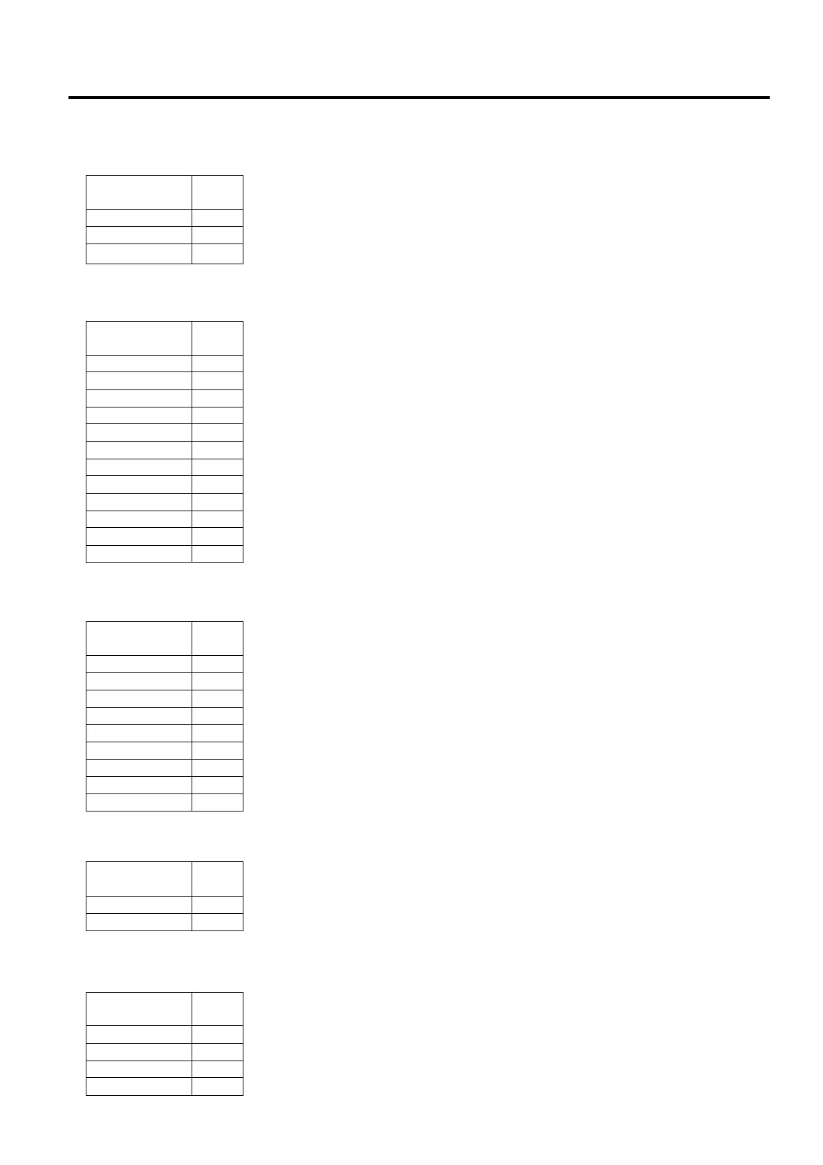
J6 (Transmissive Sensor (Lower)): This connector is connected to the Feed Gap Sensor (Lower).
J8 (Cutter Module): This connector is connected to the Cutter Module.
J9 (Panel board): This connector is connected to the Panel board.
J11 (Micro Switch): This connector is connected to the Micro Switch.
J14 (Cutter Come-off Sensor): This connector is connected to the Cutter Unit.
Signal
Pin
No.
+3.3V 1
ST MEDIA 2
N/C 3
Signal
Pin
No.
KEY1 1
N/C 2
LED 1 3
LED 2 4
+3V3 5
GND 6
LED 4 7
LED 3 8
GND 9
Signal
Pin
No.
GND 1
COVER SW 2
Signal
Pin
No.
+5V 1
GND 2
+3V3 3
PEELR 4
Signal
Pin
No.
+24V 1
GND 2
+3V3 3
GND 4
CUT ON 5
CUT DIR 6
CUT SW 7
+3V3 8
+24V 9
CTYPE 10
GND 11
+24V 12
 Loading...