2. ELECTRONICS SPECIFICATIONS EO18-33030
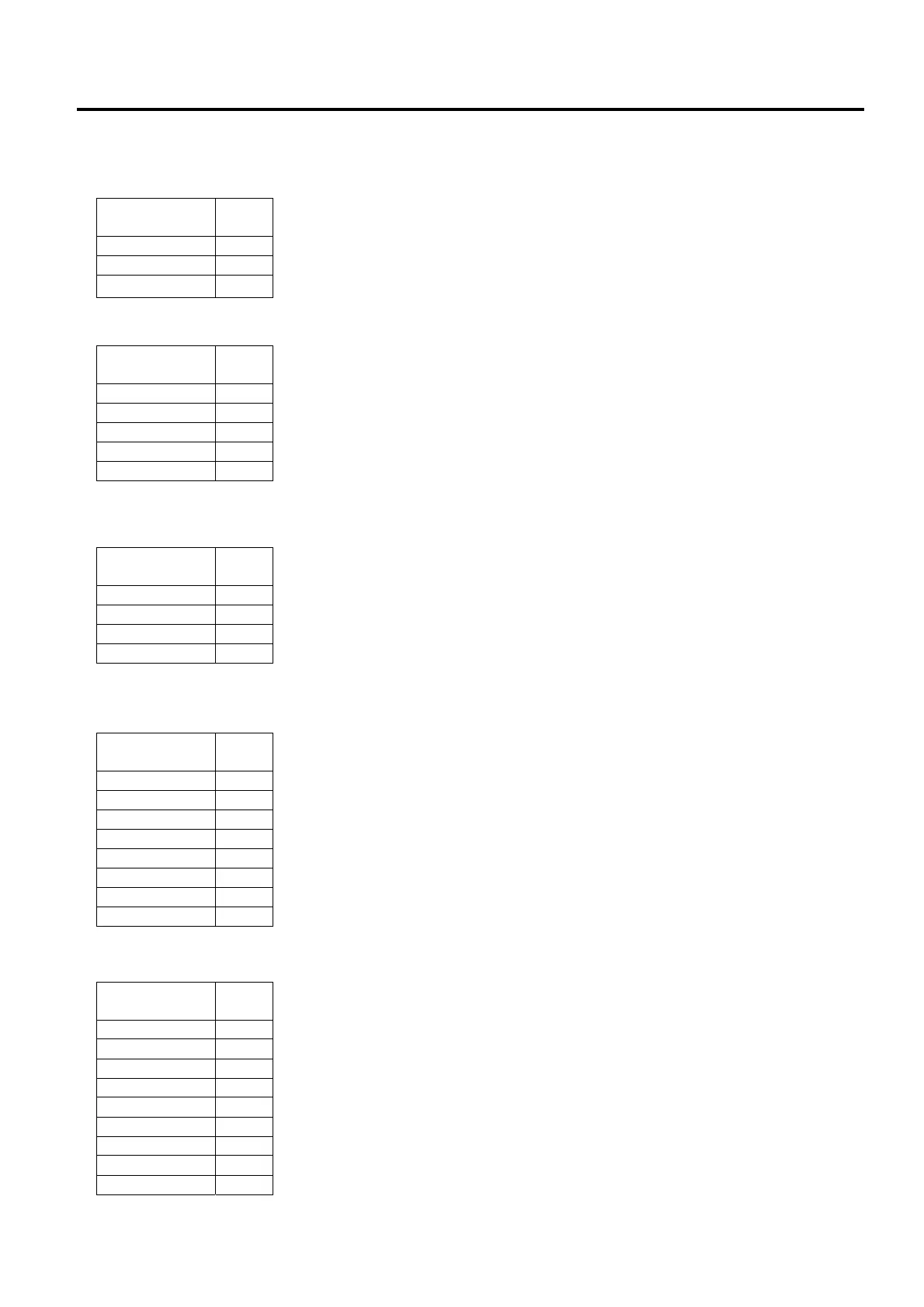
2.3 Main PC Board Connector Pin Assignment
2-20
P1 (DC Jack): This DC jack is connected to the DC plug of the AC adaptor.
P2 (USB Device port): This connector is used for the USB device port.
P3 (USB Host port): This connector is used for the USB host port.
P4 (Ethernet port): This connector is used for the Ethernet port (10/100 Base).
P5 (Serial Interface port): This connector is used for the Serial interface (RS-232C).
+5V is output from the pin 1.
The TXD signal is a serial signal and output from the pin 2.
The RXD signal is a serial signal and input into the pin 3.
Signal
Pin
No.
Power 1
GND 2
GND 3
Signal
Pin
No.
+5 V 1
D- 2
D+ 3
N/C 4
GND 5
Signal
Pin
No.
+5 V 1
HDMA 2
HDPA 3
GND 4
Signal
Pin
No.
TD+ 1
TD- 2
RD+ 3
TCT 4
N/C 5
RD- 6
RCT 7
N/C 8
Signal
Pin
No.
+5 V 1
TXD 2
RXD 3
CTS 4
GND 5
RTS 6
N/C 7
RTS 8
N/C 9
 Loading...