3. REPLACING THE IMPORTANT PARTS EO18-33030
3.1 Replacing the Parts for B-FV4T-GS/TS
3-15
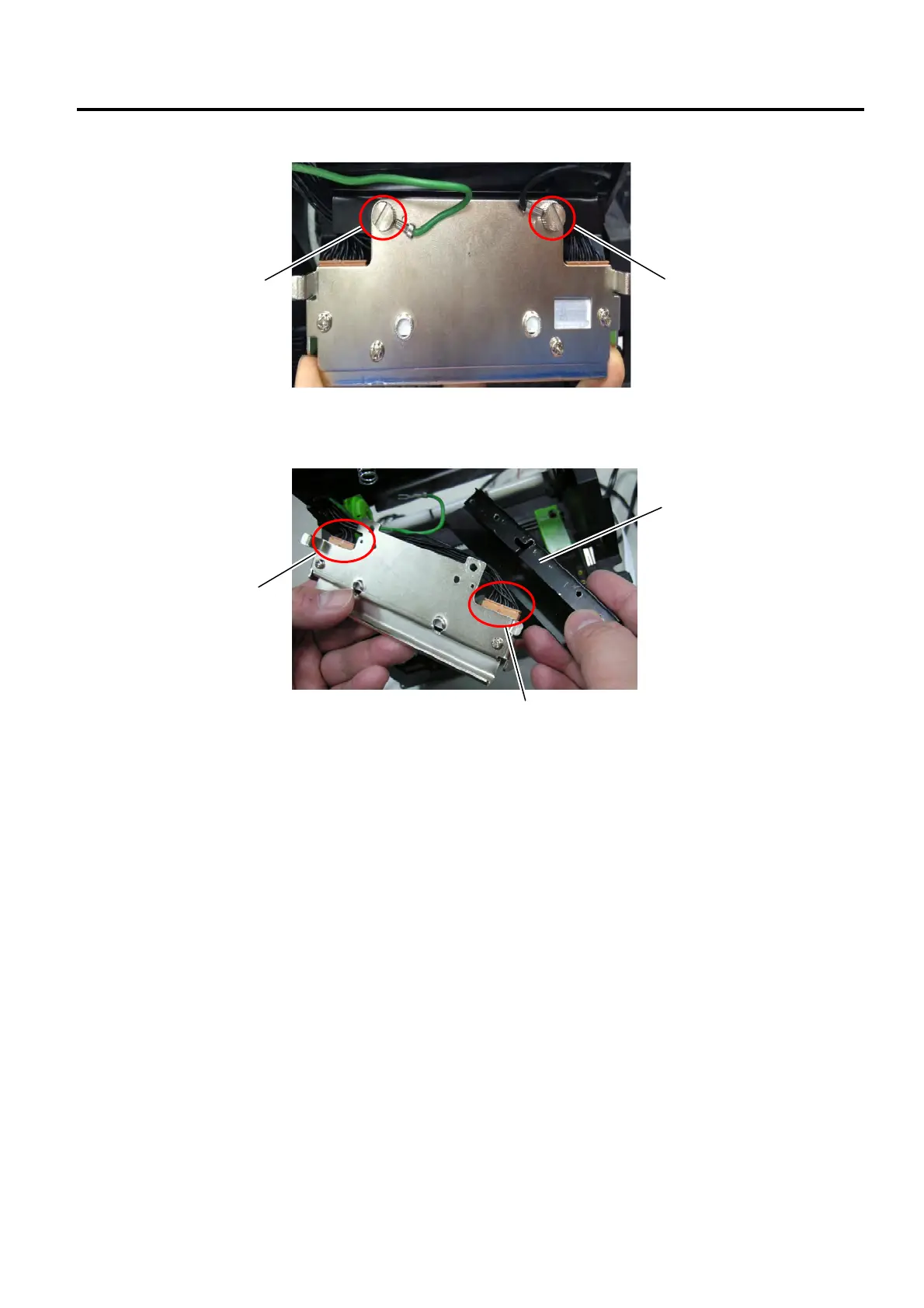
5. Use a flat screwdriver to loosen the 2 screws from the print head assembly.
6. Take out the print head cover. Disconnect the print head cables on both sides from the connectors on
the print head assembly.
7. Replace the print head assembly with a new one and then reassemble it in the reverse order of
removal.
NOTE: Do not disassemble a print head assembly containing a bracket.
8. After replacing, perform a diagnostic test print or print a sample label to make sure the printer is
performing correctly regarding the following points.
Printing is performed correctly.
No dot missing is generated.
None of blurred printing, stain, chipped bar code or characters, wrinkling, smudging, uneven
printing, etc. is generated.
Reading the bar code is possible.
Connector
Print Head Cover
Connector
Screw
Screw
 Loading...