Operation0520−1/A1
Winterthur Gas & Diesel Ltd.
2/ 4
9) Connect the electrical connection (7, Fig. 1) to the 4/2-way valve (8).
10) Start the injection (see 0510−1).
11) Do a visual check for leaks.
WCH02525
4
9
5
6
1
2
3
1
2
DRIVING END
WCH02525
1
8
7
WCH02585
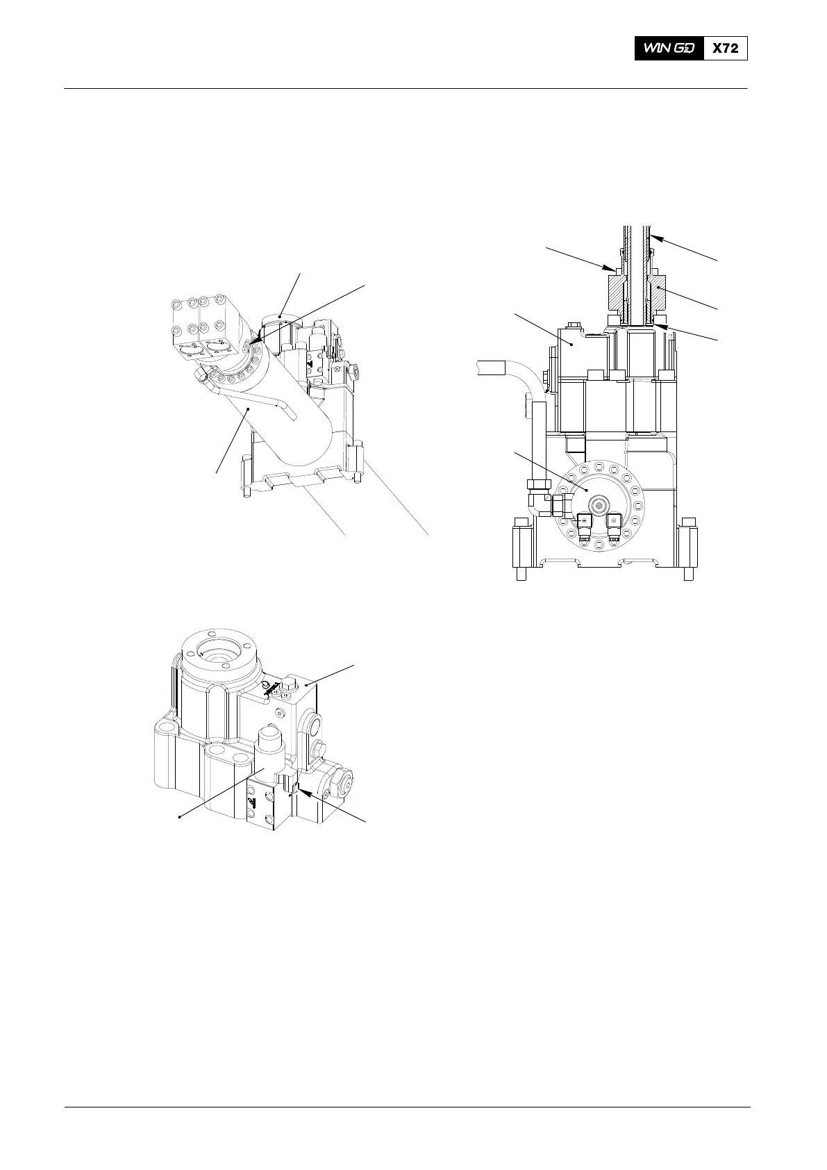
Fig. 1: Exhaust Valve Control Unit
1 Exhaust valve control unit (VCU) 5 Flange
2 Servo oil rail 6 Screw (on flange of hydraulic pipe)
3 Screw plug 7 Electrical connection
4 Hydraulic pipe 8 4/2-way valve
9 Check bore
Operation with Exhaust Valve Control Unit Cut Out
2014