Operation1903−1/A1
Winterthur Gas & Diesel Ltd.
2/ 2
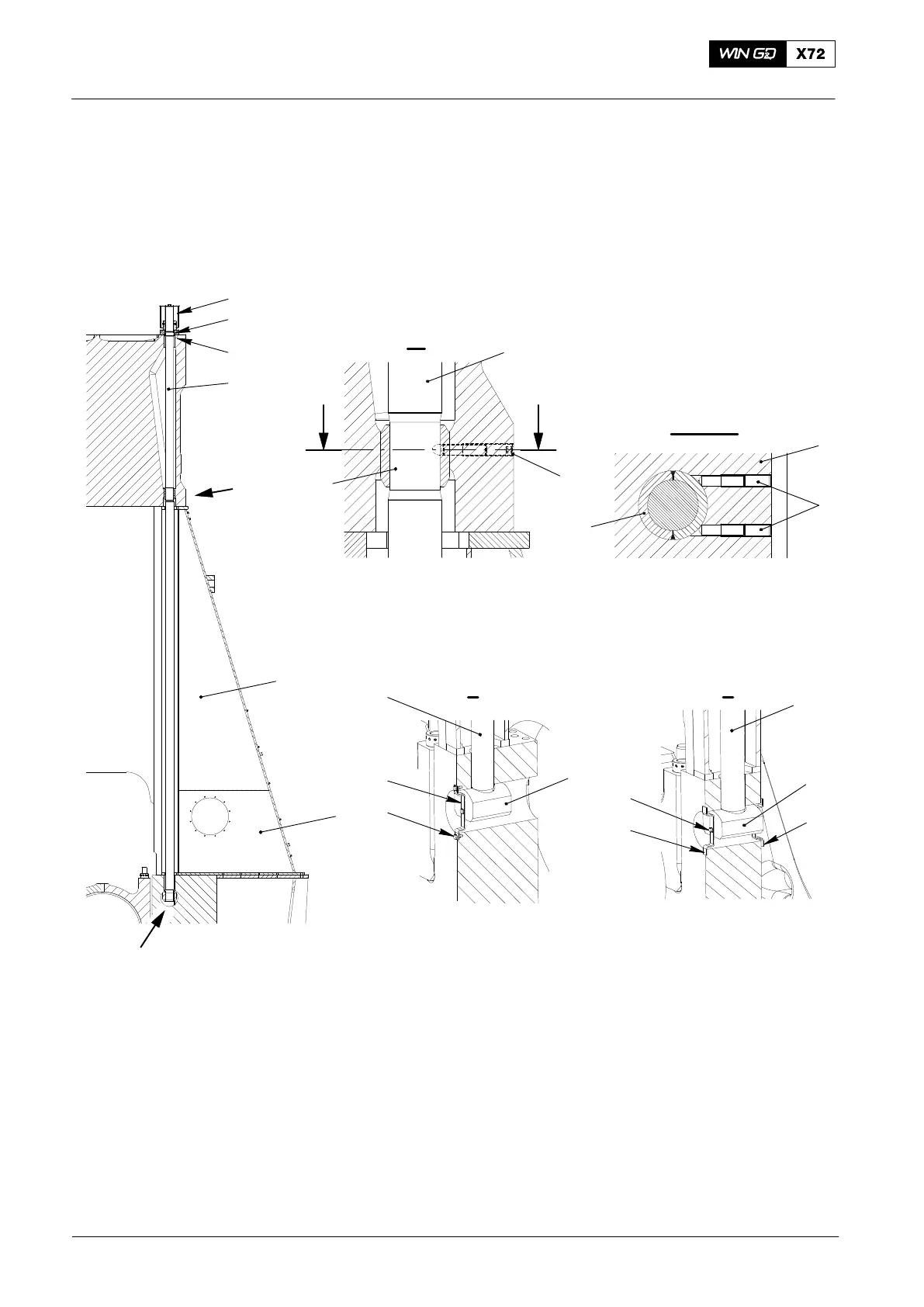
A two-part bush (8, Fig. 2) is welded on the tie rod (4). At the bottom of the cylinder
block, two set screws (7) keep the two-part bush in position to prevent vibration of the
tie rods.
If a tie rod breaks in the bottom area, the holders (11) and screws (12) make sure that
the nut (10) does not fall into the crankcase.
2
1
3
4
5
6
II
I
II
III - III
III
III
7
8
8
7
9
WCH01211
WCH01211
WCH01211
4
10
4
FREE END
11
I
10
12
DRIVING END
4
12
11
11
I
Fig. 2: Tie Rod Assembly
1 Protection cover 7 Set screw
2 Round nut 8 Two-part bush
3 Intermediate ring 9 Cylinder jacket
4 Tie rod 10 Nut
5 Column 11 Holder
6 Bedplate 12 Screw
2014
Tie Rod