Operation4002−4/A1
Winterthur Gas & Diesel Ltd.
2/ 4
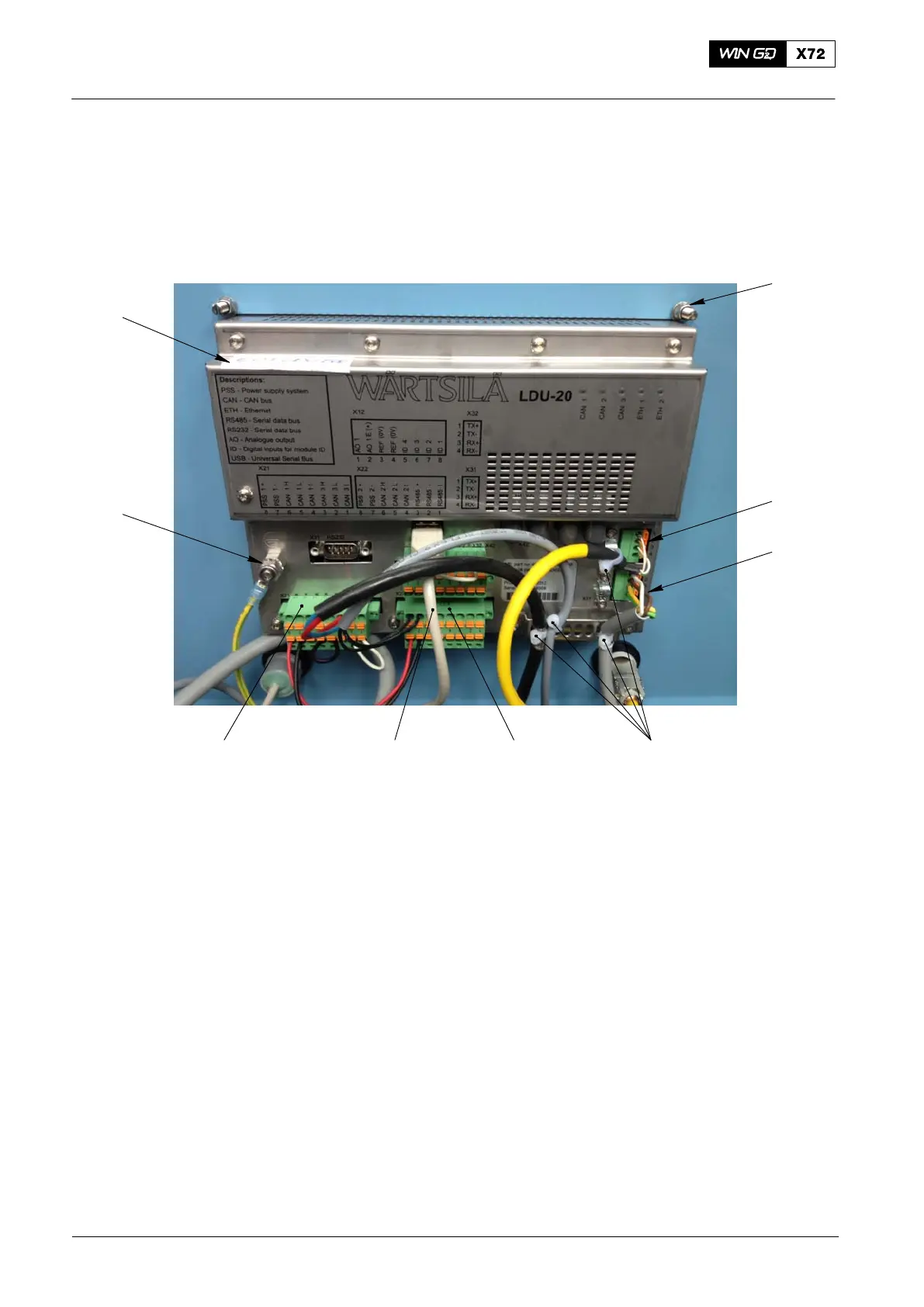
4) Record the positions of the plugs and cables that follow:
D The plug X21 (7, Fig. 2) and plug X22 (5).
D The cables of the service connection (2).
D The cables to the Ethernet connection (3).
2
3
7
1
5
8
6
9
4
WCH02715
Fig. 2: Rear View of LDU−20
5) Remove and discard the four cable ties (4).
6) Disconnect the plugs X21 (7) and X22 (5).
7) Disconnect the cables from the Ethernet connection (3).
8) Disconnect the cables from the service connection (2).
9) If installed, disconnect the USB cable (6).
10) Disconnect the earth cable (8).
11) Remove the four nuts and spring washers (1) from the studs.
12) Remove the LDU−20.
13) Attach an UNSERVICEABLE label to the LDU−20. Put the defective LDU−20 into
storage.
14) In the engine control room (ECR), get access to the rear of the LDU−20.
15) Do step 4) to step 12) to remove the LDU−20 from the ECR.
16) Attach the LDU−20 to box with the four spring washers and nuts (1).
17) Connect the earth cable (8) to the connection on the LDU−20.
ECS Modules − Replacement
2016−11