Operation9308−1/A1
Winterthur Gas & Diesel Ltd.
4/ 4
201
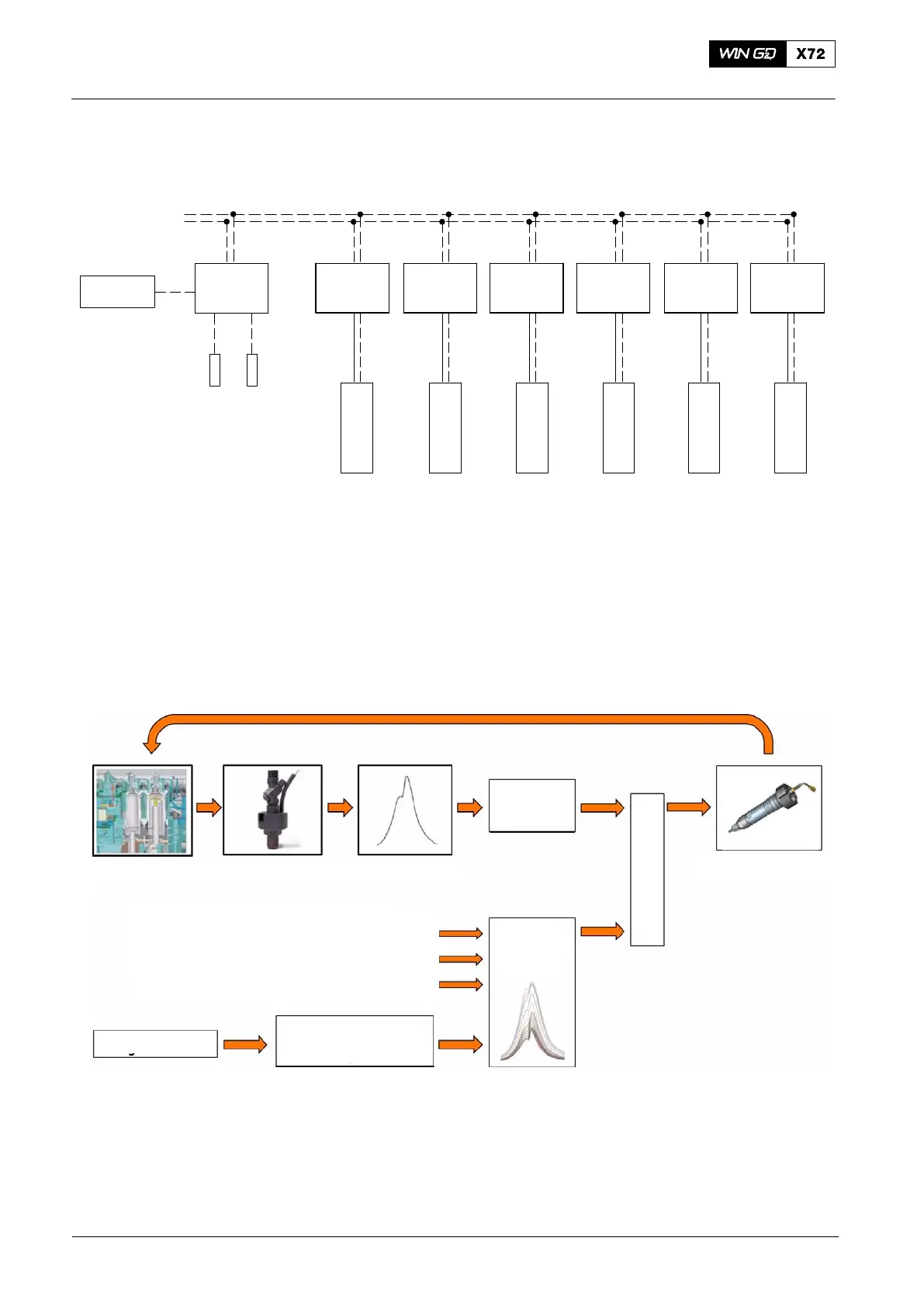
The cylinder pressure data of each cylinder is taken as an analogue input signal from
the pressure transducer into the ECS. For more data, see Fig. 3.
Barometric
pressure
IOM-10
Temperature sensor
(TC compressor inlet)
Temperature sensor
(Scavenge air receiver)
CCM−20
Cyl. 1
CCM−20
Cyl. 2
CCM−20
Cyl. 3
CCM−20
Cyl. 4
CCM−20
Cyl. 5
CCM−20
Cyl. 6
CAN System Bus
Pressure
Transducer 1
Pressure
Transducer 6
Pressure
Transducer 5
Pressure
Transducer 4
Pressure
Transducer 3
Pressure
Transducer 2
Power
Supply
DATA FOR
6 CYLINDERS
Fig. 3: Installation Schematic of the ICC System
The ECS control system filters the signals from the sensors and then transmits these
signals to a controller. The measured value is adjusted to the correct set-point value
and is related to the engine load. This real-time site correction and
comparison is done for each engine cycle (see Fig. 4).
Setpoint
Correction
TC compressor inlet air temperature
Scavenge air temperature
TC compressor inlet pressure
Value
Firing Pressure
Setpoint
Engine Load
Comparison
Combustion Cylinder pressure evaluation
Injection start offset
Fig. 4: Control schematic of the ICC System
2014