06/2014
6-40
WC 5022/5024
6.3.6.2 NVM IIT
Version 1.0
General
710-608Alternate Size Set 8 040OSwitches among B4 SEF and 11x17 SEF.
0: Default
1: B4 SEF
2:11x17 SEF
710-609Alternate Size Set 9 020OSwitches between 8x10 SEF and 8x10.5 SEF.
0: Default
1: 8x10 SEF
2: 8x10.5 SEF
710-610Alternate Size Set 10 030OSwitches between B5 LEF and 8.5x11 LEF.
0: Default
1: B5 LEF
2: 8.5x11 LEF
710-611Alternate Size Set 11 030OSwitches between B5 SEF and 8.5x11 SEF.
0: Default
1: B5 SEF
2: 8.5x11 SEF
710-612 Size-Mix Mode Assumed Size 011OSwitches between LEF and SEF
0: LEF
1: SEF
710-613Fixed Size Selection 010ODuring Fax Mixed Size Mode, switches the size (Standard/Non-standard) noti-
fied to IISS from the DADF.
0: Non-standard mode
1: Standard mode
710-620 DADF Dpm Specification 0 65535 0 O Specifies the DPM for DADF.
0: Operates at the maximum performance DPM of DADF
1~65535: Operates at the specified DPM (in increments of 1 DPM)
715-010Energy Saver Disable 010OWhen Setting Value: 0,
At Power OFF: Move the CRG to the W-Ref board position. *Note
At Power ON: Initialize the CRG.
Returning from Energy Saver: Do not initialize the CRG.
When Setting Value: 1,
At Power OFF: Do not move the CRG.
At Power ON: Initialize the CRG.
Returning from Energy Saver: Initialize the CRG.
*Depending on the setting value of 719-999, there might be no movement
instead.
For more details, refer to the Meaning column of 719-999.
715-017IIT Fail Bypass 010O0: Fail Bypass OFF
1: Fail Bypass ON
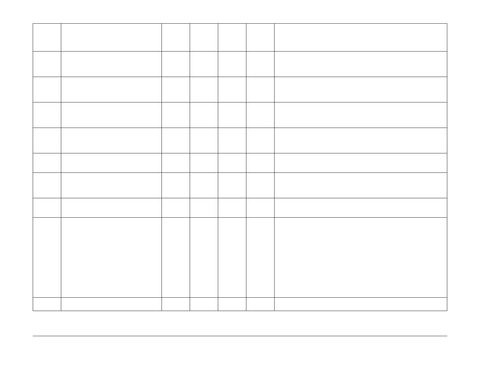
Table 1 NVM IIT
Chain-Link NVM Name
Setting
Range
(Minimum
Value)
Setting
Range
(Maximum
Value)
Default
Value Read/Write Description
 Loading...