06/2014
9-10
WC 5022/5024
9.1.6 Stand
Version 1.0
Installation/Removal
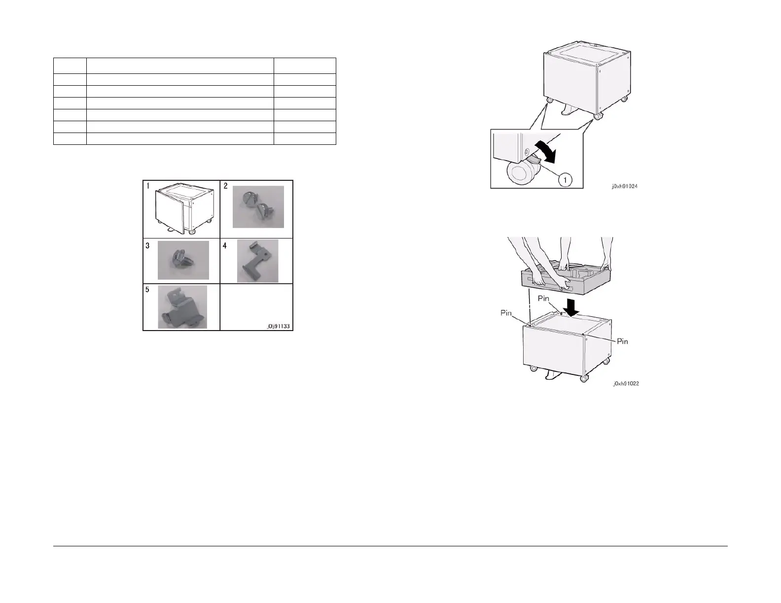
• Stand (Figure 2)
• There is no illustration for Item 6
Figure 2 j0lj91133
3. Remove the packaging tapes and materials from the One Tray Module and the Stand.
4. Turn OFF the power switch and make sure that the screen display turns OFF.
CAUTION
When turning OFF the power switch, check that the "Data" lamp is OFF and that there is
no Job in progress.
5. Unplug the power plug.
WARNING
When maintaining the machine, turn OFF the power switch and unplug the power
plug.
6. Disconnect all cables that are connected to the right of the IOT.
7. Lower the lever of the caster (x2) at the front of the Stand to lock them. (Figure 3)
a. Lock the caster (x2).
Figure 3 j0xh91024
8. Align the One Tray Module to the positioning pin (x3) of th Stand and mount it. (Figure 4)
Figure 4 j0xh91022
9. Pull out and remove Tray 2 of the One Tray Module.
10. Secure the One Tray Module to the Stand by using the Docking Screw (x2). (Figure 5)
a. Secure it by using the Docking Screw (x2).
Table 2
No Name Qty
1 Stand 1
2 Docking Screw 2
3 Screw 1
4 Joint 1
5 Bracket (Not used) -
6 Installation Guide 1
 Loading...