4.7 Operation Sequence
4-63
4
4.7 Operation Sequence
This section describes outline of the operation sequence. Refer to 4.3 Main Commands and 4.4
Subcommands for details of command functions and settings.
4.7.1 Operation Sequence for Managing Parameters Using a Controller
The following describes the operation sequence for managing parameters using a controller.
The controller manages the necessary parameters, and transfers them when the power is
turned ON. With this operation sequence, the settings can be managed by the controller even
when the SERVOPACK is replaced.
* If communication disconnects normally, the NOP command is sent. If communication does not
disconnect normally, the DISCONNECT command is sent for two or more communications
cycles prior to connection, then the CONNECT command is sent.
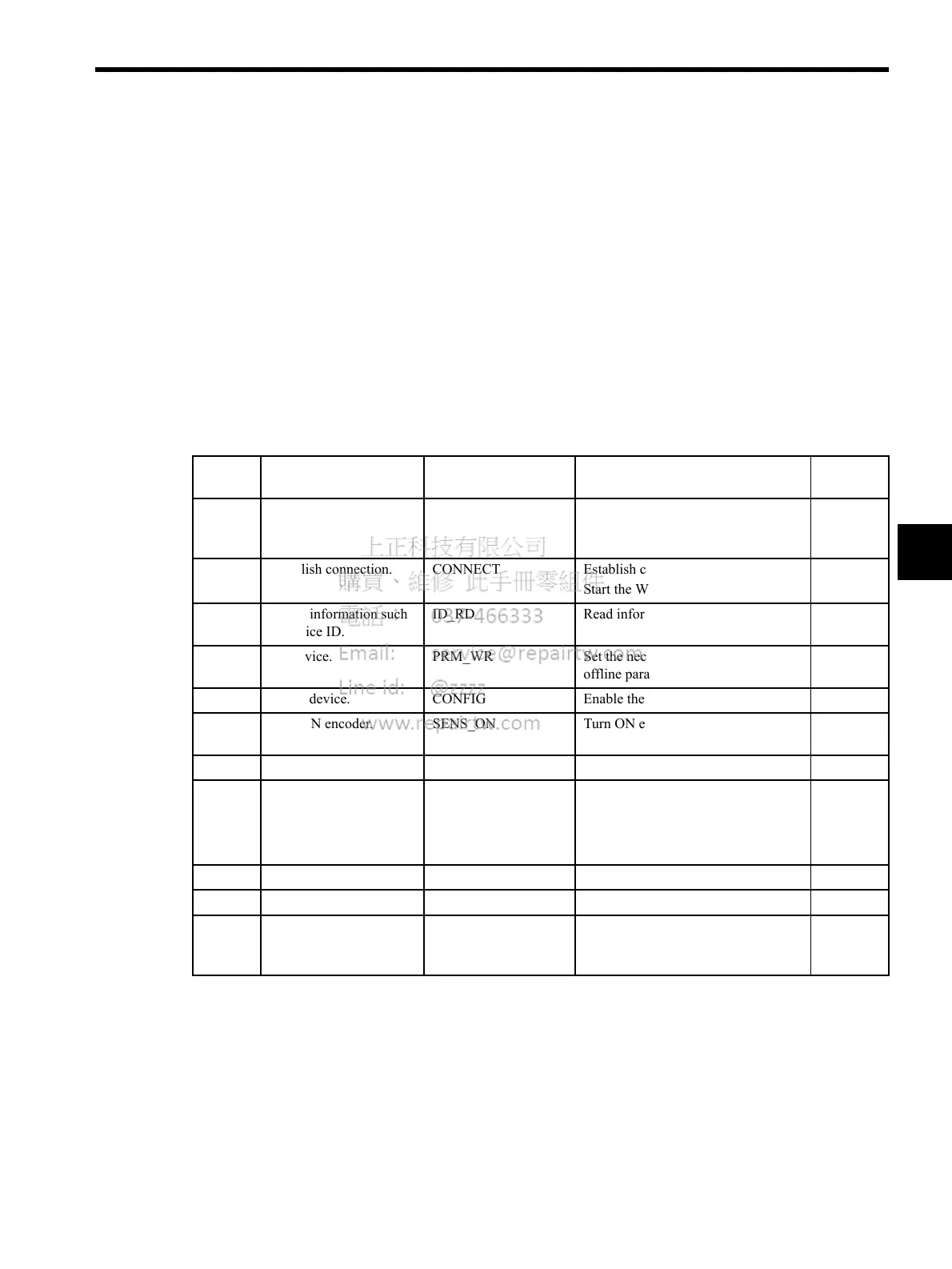
Table 4.4 Operation Sequence for Managing Parameters Using a Controller
Proce-
dure
Item Command Description Phase
1 Turn ON control and
main circuit power sup-
plies.
NOP/DISCONNECT* Turn ON power supplies.
1
2 Establish connection. CONNECT Establish communications.
Start the WDT count.
2 or 3
3 Check information such
as device ID.
ID_RD Read information such as device type.
2 or 3
4 Set device. PRM_WR Set the necessary parameters such as
offline parameters.
2 or 3
5 Set up device. CONFIG Enable the parameter settings.
2 or 3
6 Turn ON encoder. SENS_ON Turn ON encoder and obtain the posi-
tion data.
2 or 3
7 Operate main circuit. SV_ON Turn ON servomotor.
2 or 3
8 Start operation.
.
.
.
.
.
.
Start operation.
.
.
.
2 or 3
9 Turn OFF main circuit. SV_OFF Turn OFF servomotor.
2 or 3
10 Disconnect connection. DISCONNECT Disconnect communications.
4
to 1
11 Turn OFF control and
main circuit power sup-
plies.
− Turn OFF power supplies.
5

 Loading...


