B.2 Function Switches
B-9
B
B.2 Function Switches
The following list shows the function switches and their settings.
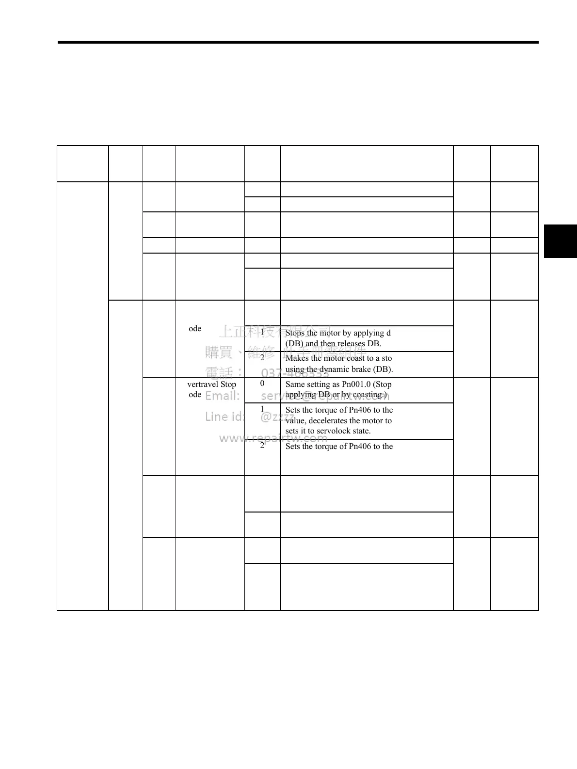
Table B.3 Function Switches List
Category Pn No. Digit
Place
Name Setting Description SGDH
Factory
Setting
Changing
Method *
Function
Switches
Pn000 0 Direction
Selection
0
Sets CCW as forward direction.
0
∆
1
Sets CW as forward direction.
1
Control Method
Selection
0 to B
Settings are invalid. Do not set.
0
∆
2 Axis Address
0 to F
Sets the SERVOPACK axis address.
0
∆
3 Rotary/Linear
Startup Selection
(when encoder is
not connected)
0
Starts up as rotary motor.
0
∆
1
Starts up as linear motor.
Pn001 0 Servo OFF or
Alarm Stop
Mode
0
Stops the motor by applying dynamic brake
(DB).
0
∆
1
Stops the motor by applying dynamic brake
(DB) and then releases DB.
2
Makes the motor coast to a stop state without
using the dynamic brake (DB).
1 Overtravel Stop
Mode
0
Same setting as Pn001.0 (Stops the motor by
applying DB or by coasting.)
0
∆
1
Sets the torque of Pn406 to the maximum
value, decelerates the motor to a stop, and then
sets it to servolock state.
2
Sets the torque of Pn406 to the maximum
value, decelerates the motor to a stop, and then
sets it to coasting state.
2 AC/DC Power
Input Selection
0
Not applicable to DC power input: Input AC
power supply through L1, L2, and (L3) termi-
nals.
0
∆
1
Applicable to DC power input: Input DC
power supply through (+)1 and (-) terminals.
3 Warning Code
Output Selection
0
ALO1, ALO2, and ALO3 output only alarm
codes.
0
∆
1
ALO1, ALO2, and ALO3 output both alarm
codes and warning codes. While warning codes
are output, ALM signal output remains ON
(normal state).

 Loading...


