6 Parameter Setting and Functions
6.4.3 Output Circuit Signal Allocation
6-34
6.4.3 Output Circuit Signal Allocation
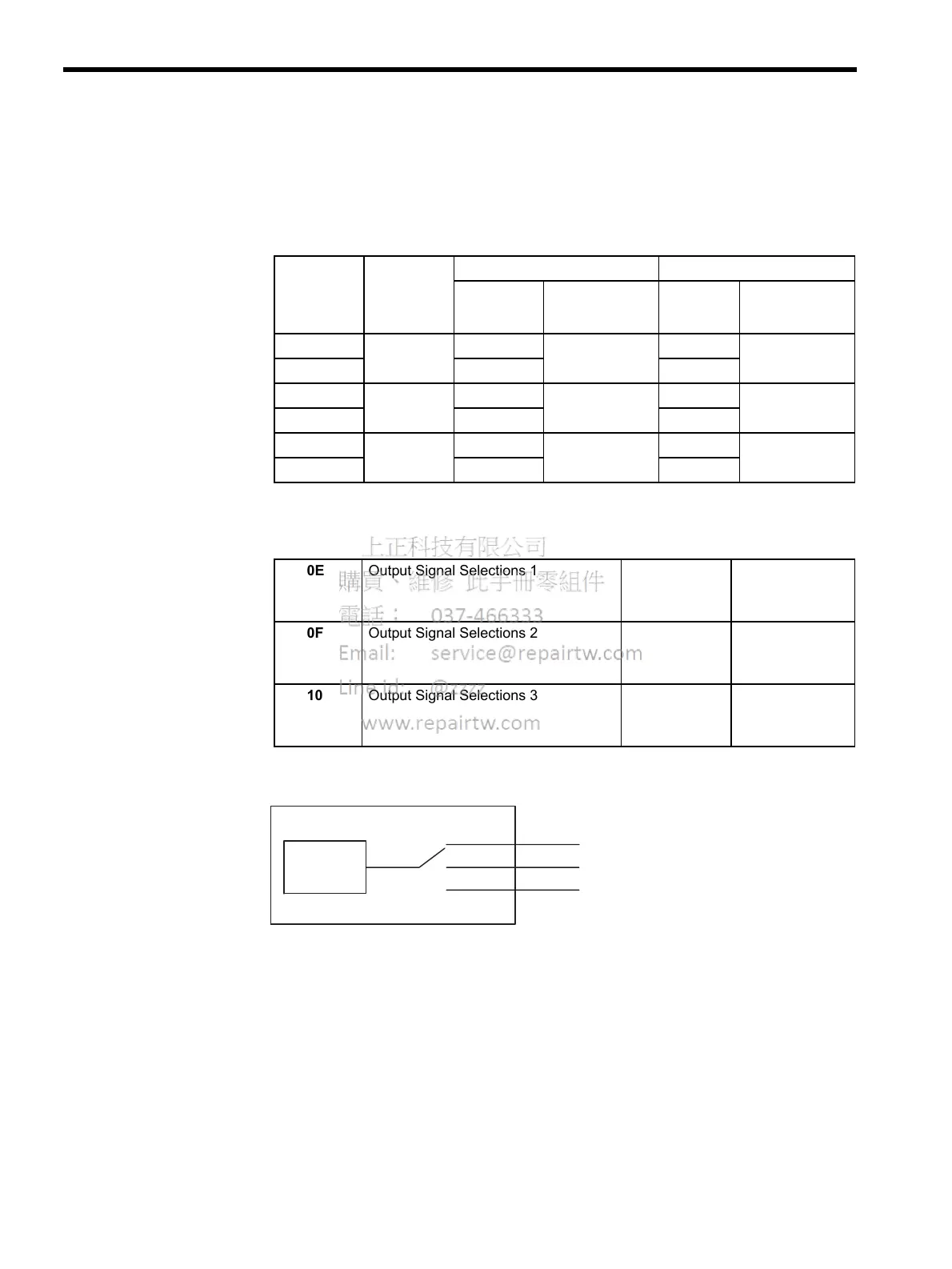
Output signal functions can be allocated to the sequence signal output circuits shown below.
In general, allocate signals according to the standard settings in the following table.
The output signal selection parameters and their factory settings and standard settings are
shown below.
Select the CN1 connector terminals that will output the signals.
CN1
Connector
Ter m in al
Numbers
Output
Terminal
Name
Factory Setting Standard Setting
Symbol Name Symbol Name
25
SO1 /COIN+ Positioning com-
pleted
/COIN+ Positioning com-
pleted
26
/COIN- /COIN-
27
SO2 /TGON+ Rotation detec-
tion
/BK+ Brake interlock
28
/TGON- /BK-
29
SO3 /S-RDY+ Servo ready /S-RDY+ Servo ready
30
/S-RDY- /S-RDY-
Pn50E Output Signal Selections 1 Factory
Setting:
3211
Standard
Setting:
3001
Pn50F Output Signal Selections 2 Factory
Setting:
0000
Standard
Setting:
0200
Pn510 Output Signal Selections 3 Factory
Setting:
0000
Standard
Setting:
0000
1
2
3
Output
signal
SO1(CN1-25,26)
SO2(CN1-27,28)
SO3(CN1-29,30)
Pn50E. to Pn510.

 Loading...


