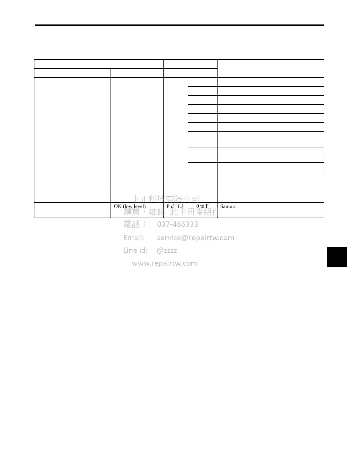
6.4 Setting Up the SERVOPACK
6-33
6
External Latch Signal 1
(/EXT1)
ON (low level) Pn511.1
0 to 3
Sets the signal on the left to always disabled.
4
Inputs the signal on the left from SI4 (CN1-44).
5
Inputs the signal on the left from SI5 (CN1-45).
6
Inputs the signal on the left from SI6 (CN1-46).
7
Sets the signal on the left to always enabled.
8
Sets the signal on the left to always disabled.
D
Inputs the reverse of the signal on the left from
SI4 (CN1-44).
E
Inputs the reverse of the signal on the left from
SI5 (CN1-45).
F
Inputs the reverse of the signal on the left from
SI6 (CN1-46).
9 to F
Sets the signal on the left to always disabled.
External Latch Signal 2
(/EXT2)
ON (low level) Pn511.2
0 to F
Same as above.
External Latch Signal 3
(/EXT3)
ON (low level) Pn511.3
0 to F
Same as above.
(cont’d)
Input Signal Parameter Description
Name Applicable Logic Number Setting

 Loading...


