6 Parameter Setting and Functions
6.3.3 Acceleration/Deceleration Function
6-22
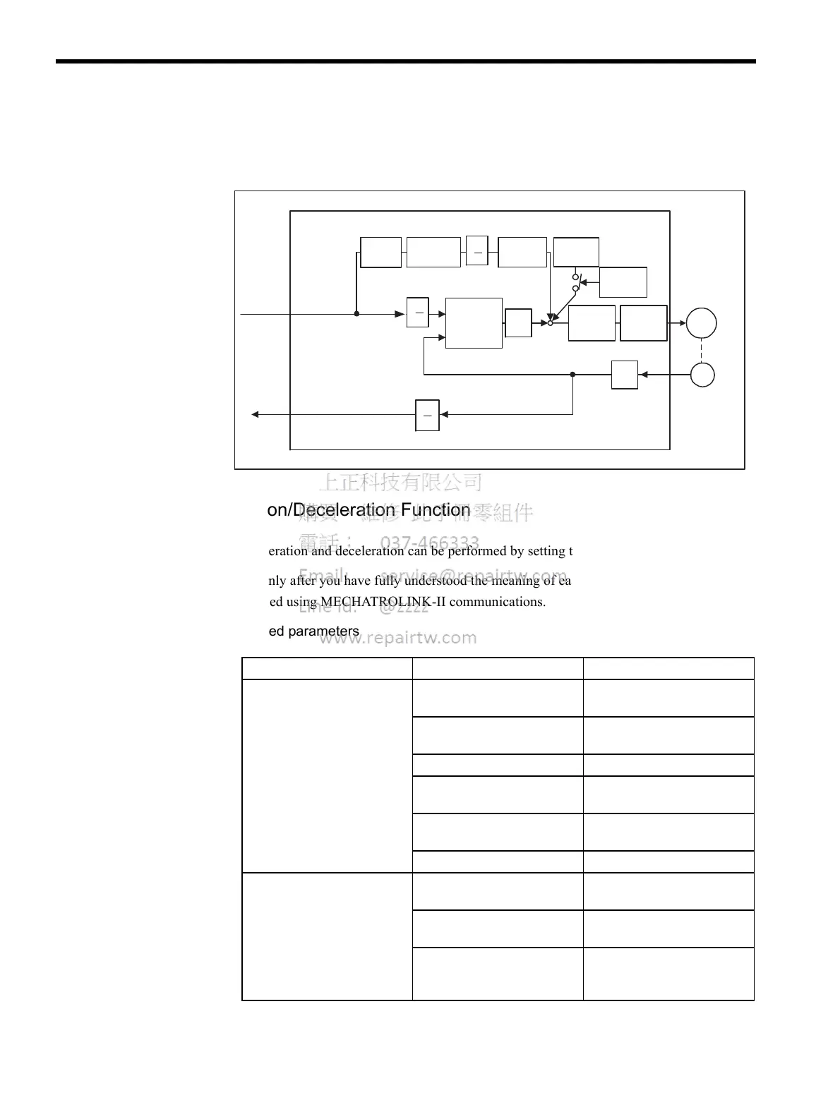
Control Block Diagram
The following diagram illustrates a control block for position control.
6.3.3 Acceleration/Deceleration Function
Acceleration and deceleration can be performed by setting the following parameters.
Use only after you have fully understood the meaning of each parameter. Settings are
changed using MECHATROLINK-II communications.
Related parameters
Differ-
entiation
Error
counter
Kp
Feed-
forward gain
Primary
lag filter
Bias
Speed
loop
Current
loop
M
Pn203
Pn202
Pn203
+
-
Pn102
Pn203
Pn202
Pn10A
Pn107Pn109
Servomotor
PG
Position
data inter-
polation
SERVOPACK (position control)
Encoder
Bias
addition
range
Pn108
B
A
B
A
+
++
Position
data
A
B
Pn202
× 4
Type Pn No. Outline
Acceleration/deceleration Pn80A
First-step linear acceleration
parameter
Pn80B
Second-step linear acceleration
parameter
Pn80C
Acceleration switching speed
Pn80D
First-step linear deceleration
parameter
Pn80E
Second-step linear deceleration
parameter
Pn80F
Deceleration switching speed
Position reference filter Pn810
Exponential position reference
filter bias
Pn811
Exponential position reference
filter time constant
Pn812
Movement average time of
movement average position
reference filter

 Loading...


