3.3 I/O Signals
3-7
3
3.3.2 I/O Signals Connector (CN1)
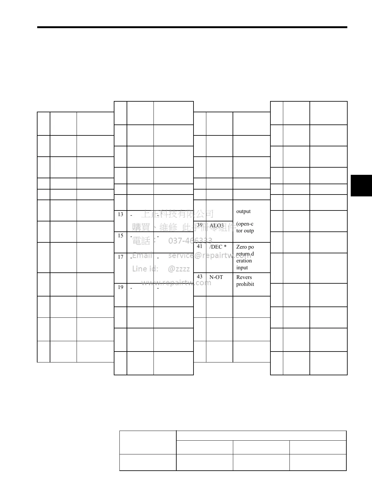
The following diagram shows the layout of CN1 terminals.
CN1 Terminal Layout
* Make signal allocations using parameters. (Refer to 6.1.2 Standard Settings for CN1 I/O Signals.)
Note: 1. Do not use unused terminals for relays.
2. Connect the shield of the I/O signal cable to the connector shell.
The shield is connected to the FG (frame ground) at the SERVOPACK-end connector.
CN1 Specifications
1
SG GND
26
/COIN- Positioning
complete
output
2
SG GND
27
/BK+ * Brake inter-
lock output
3
--
28
/BK- * Brake inter-
lock output
4
--
29
/S-
RDY+
Servo ready
output
5
--
30
/S-RDY- Servo ready
output
6
SG GND
31
ALM+ Servo alarm
output
7
--
32
ALM- Servo alarm
output
8
--
33
--
9
--
34
--
10
SG GND
35
--
11
--
36
--
12
--
37
ALO1 Alarm code
output
(open-collec-
tor output)
13
--
38
ALO2 Alarm code
output
14
--
39
ALO3
15
--
40
--
16
--
41
/DEC * Zero point
return decel-
eration LS
input
17
--
42
P-OT Forward drive
prohibited
input
18
--
43
N-OT Reverse run
prohibited
input
19
--
44
/EXT1 * External latch
signal 1 input
20
--
45
/EXT2 * External latch
signal 2 input
21
BAT (+) Battery (+)
46
/EXT3 * External latch
signal 3 input
22
BAT (-) Battery (-)
47
+24VIN External
power supply
input
23
--
48
--
24
--
49
--
25
/COIN + Positioning
complete
output
50
--
Specifications for
SERVOPACK
Connectors
Applicable Receptacles
Soldered Case Manufacturer
10250-52A2JL 50-p
Right Angle Plug
10150-3000VE 10350-52A0-008 Manufactured by
Sumitomo 3M Ltd.

 Loading...


