3.4 Fully Closed Encoder Signals Connector (CN4)
3-11
3
3.4 Fully Closed Encoder Signals Connector (CN4)
This section describes the wiring for the fully closed encoder signals connector (CN4).
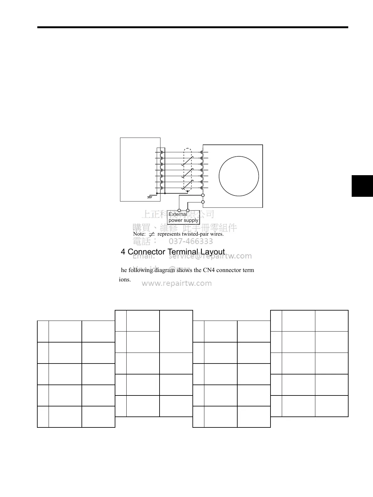
3.4.1 Fully Closed Encoder Connection Example
The following diagram shows an example of CN4 connections.
Note: represents twisted-pair wires.
3.4.2 CN4 Connector Terminal Layout
The following diagram shows the CN4 connector terminal layout and connector specifica-
tions.
CN4 Connector Terminal Layout
Note: 1. The connector shell is connected to the FG (frame ground).
2. Do not use unused terminals as relay terminals.
External
powersupply
External PG
GND
A
/A
B
/B
Z
/Z
PG0V
/FC
17
18
19
14
15
1,2,3
NS115
16
FA
/FA
CN4
FB
/FB
FC
1
PG0 V Signal
ground
11
--
2
PG0 V Signal
ground
12
--
3
PG0 V
13
--
4
--
14
FC Phase-C
input
5
--
15
/FC Phase-C
input
6
--
16
FA Phase-A
input
7
--
17
/FA Phase-A
input
8
--
18
FB Phase-B
input
9
--
19
/FB Phase-B
input
10
--
20
--

 Loading...


