3.3 I/O Signals
3-9
3
3.3.4 Interface Circuits
This section shows examples of SERVOPACK I/O signal connection to the host controller.
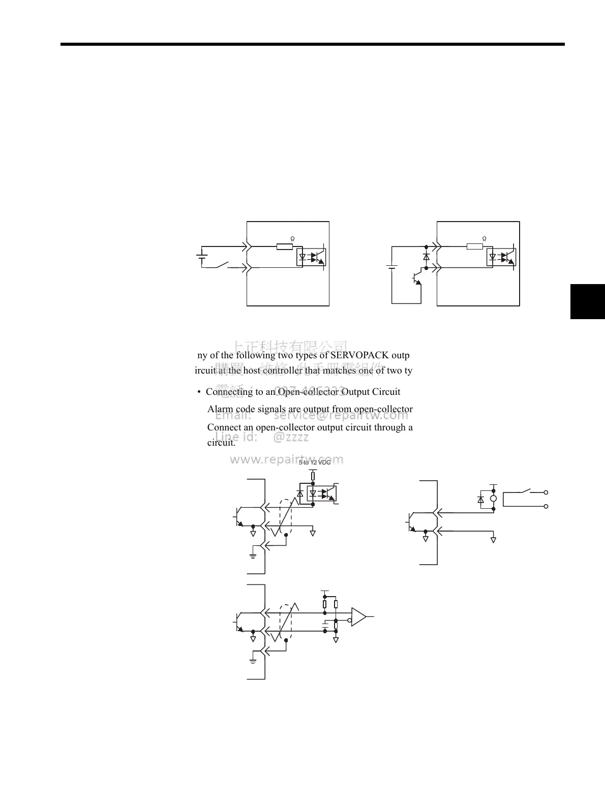
Sequence Input Circuit Interface
The sequence input circuit interface connects through a relay or open-collector transistor cir-
cuit. Select a low-current relay, otherwise a faulty contact will result.
Output Circuit Interfaces
Any of the following two types of SERVOPACK output circuits can be used. Form an input
circuit at the host controller that matches one of two types.
• Connecting to an Open-collector Output Circuit
Alarm code signals are output from open-collector transistor output circuits.
Connect an open-collector output circuit through a photocoupler, relay or line receiver
circuit.
Note: The maximum allowable voltage and current capacities for open-col-
lector output circuits are as follows:
• Voltage: 30VDC max.
• Current: 20 mA DC max.
• Connecting to a Photocoupler Output Circuit
/DEC, etc.
/DEC, etc.
SERVOPACK
SERVOPACK
24 VDC
50 mA min.
24 VDC
50 mA min.
3.3 k
+24 VIN
3.3 k
+24 VIN
Photocoupler
Relay
5 to 12 VDC
5 to 12 VDC
5 to 12 VDC
0V0V
0V
0V
0V
0V
SERVOPACK
end
SERVOPACK
end

 Loading...


