6.4 Setting Up the SERVOPACK
6-29
6
6.4 Setting Up the SERVOPACK
This section describes the procedure for setting parameters to operate the SERVOPACK.
6.4.1 Parameters
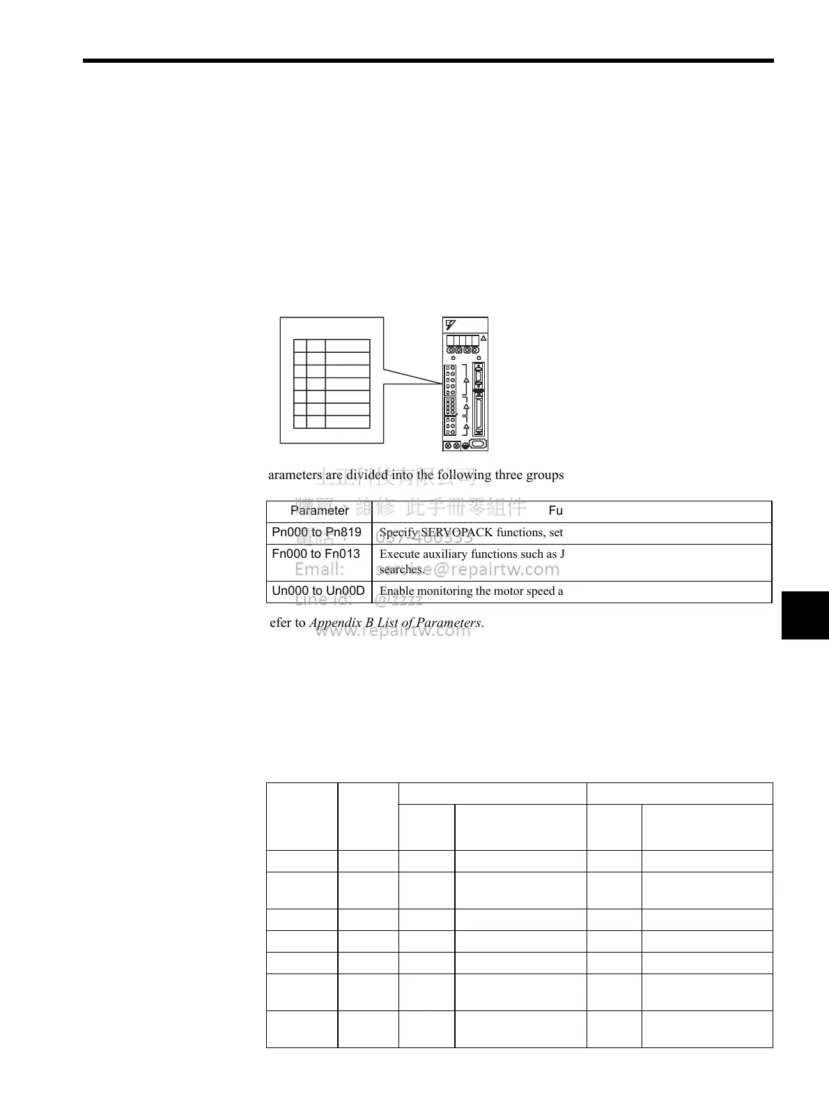
The Σ-ΙΙ Series SERVOPACK provides many functions and has parameters called parame-
ters that allow the user to specify functions and perform fine adjustments.
Parameters are divided into the following three groups.
Refer to Appendix B List of Parameters.
6.4.2 Input Circuit Signal Allocation
The functions allocated to sequence input signal circuits can be changed. CN1 connector
input signals are allocated with the factory settings as shown in the following table.
In general, allocate signals according to the standard settings in the following table.
Parameter Function
Pn000 to Pn819 Specify SERVOPACK functions, set servo gains, etc.
Fn000 to Fn013 Execute auxiliary functions such as JOG Mode operations and zero-point
searches.
Un000 to Un00D Enable monitoring the motor speed and torque reference on the panel display.
SERVOPACK
Parameters
A Panel Operator, Digital Operator, or MECHATROLINK-II
commands are used to set parameters.
CN1
Connector
Terminal
Numbers
Input
Terminal
Name
Factory Setting Standard Setting
Symbol Name Symbol Name
40
SI0 −− −−
41
SI1 −− /DEC Zero point return decel-
eration LS
42
SI2 P-OT Forward run prohibited P-OT Forward run prohibited
43
SI3 N-OT Reverse run prohibited N-OT Reverse run prohibited
44
SI4 −− /EXT1 External latch signal 1
45
SI5 /P-CL Forward run external
torque control
/EXT2 External latch signal 2
46
SI6 /N-CL Reverse run external
torque control
/EXT3 External latch signal 3

 Loading...


