3.5 Connections for MECHATROLINK-II Communications
3-13
3
3.5 Connections for MECHATROLINK-II Communications
This section describes the connection and wiring of connectors for MECHATROLINK-II com-
munications.
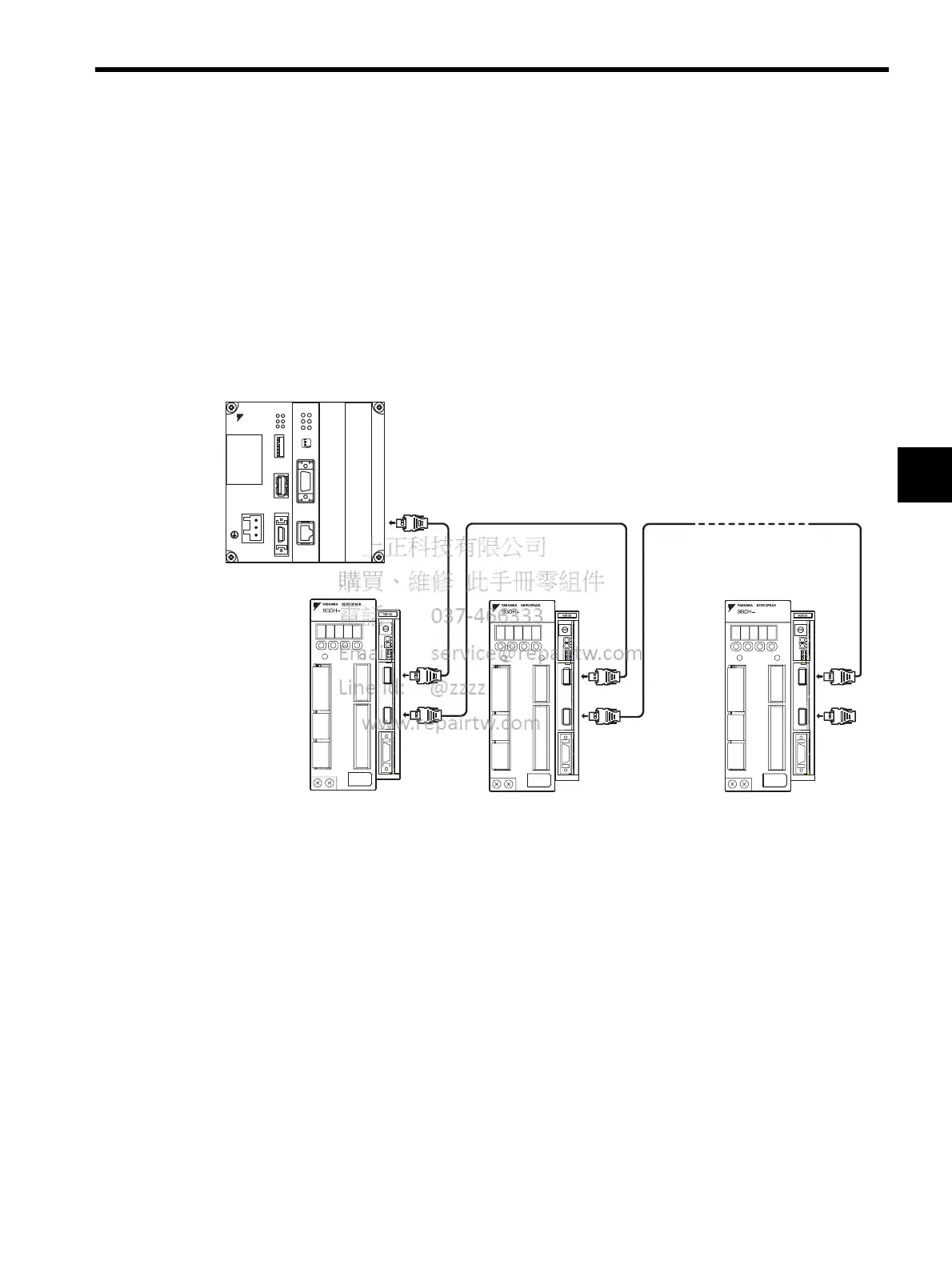
3.5.1 MECHATROLINK-II Communications Connection Example
The following diagram shows an example of connections between a host controller and a
SERVOPACK using MECHATROLINK-II communications cables (CN6A, CN6B).
Note: 1. The length of the cable between stations (L1, L2, ... Ln) must be
0.5 m or more.
2. L1 + L2 ... + Ln must be 50 m or less.
Hostcontroller
L1 LnL2
Terminator
DC24V
DC0V
MP2300
YASKAWA
TEST
Option
Option
RDY
ALM
TX
RUN
ERR
BAT
MON
CNFG
INT
SUP
STOP
SW1
OFF ON
BATTERY
CPUI/O
M-I/II
218IF-01
ERR
COL
RX
RUN
STRX
TX
INIT
TEST
ONOFF
PORT
10Base-T

 Loading...


