6.3 Settings According to Host Controller
6-17
6
The external power supply input terminal is common to sequence input signals.
Contact input signals: /DEC (CN1-41)
P-OT (CN1-42)
N-OT (CN1-43)
/EXT1 (CN1-44)
/EXT2 (CN1-45)
/EXT3 (CN1-46)
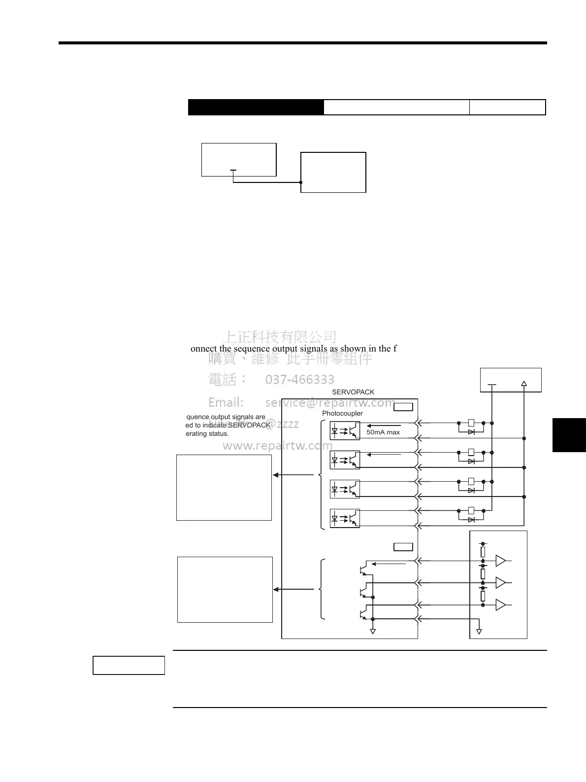
Output Signal Connections
Connect the sequence output signals as shown in the following figure. (Standard settings)
Provide a separate external I/O power supply; the SERVOPACK does not have an internal 24-V power
supply. Yaskawa recommends using the same type of external power supply as that used for input cir-
cuits.
→ Input +24VIN CN1-47 External I/O Power Supply Input Position Control
+24VIN
CN1-47
Connect an external I/O power supply.
I/O power supply
+24V
SERVOPACK
Host
controller
SERVOPACK
Photocoupler
32
31
26
25
28
27
30
29
CN1
ALO1
ALO2
ALO3
39
38
37
1
SG
CN1
+24 V 0V
0V 0V
20mA max.
/S- RDY
-
/S- RDY+
/BK
-
/BK+
/COIN
-
/COIN+
ALM
-
ALM
+
50mA max.
50mA max.
Sequence output signals are
used to indicate SERVOPACK
operating status.
Photocoupler output
per output
Maximum operating
voltage: 30 VDC
Maximum output current:
50 mA DC
I/O power supply
Open-collector output
per output
Maximum operating
voltage: 30 VDC
Maximum output current:
20 mA DC
IMPORTANT

 Loading...


