9.1 Motion Control Block Diagrams
9-15
9
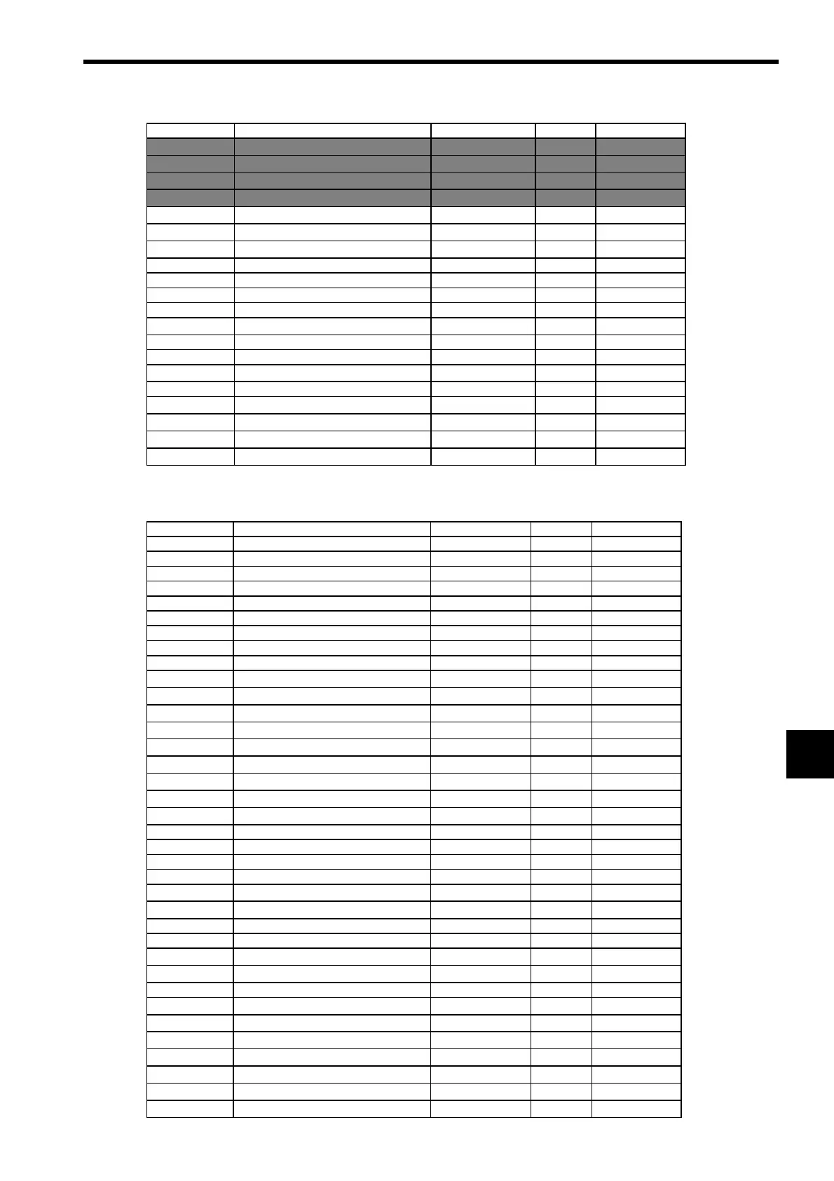
Note: The shaded parameter settings are ignored.
(c) Monitoring Parameters
OL
40 Creep Speed Depends on speed unit. 500
−
2
31
to 2
31
−
1
OL
42 Home Offset Reference unit 0
−
2
31
to 2
31
−
1
OL
44 Step Distance Reference unit 1,000
0 to 2
31
−
1
OL
46 External Positioning Move Distance Reference unit 0
−
2
31
to 2
31
−
1
OL
48 Zero Point Offset Reference unit 0
−
2
31
to 2
31
−
1
OL
4A Work Coordinate System Offset Reference unit 0
−
2
31
to 2
31
−
1
OL
4C Preset Data of POSMAX Turn Rev 0
−
2
31
to 2
31
−
1
OW
4E Servo User Monitor − 0E00 h Bit Setting
OW
4F Servo Alarm Monitor Number − 0 0 to 10
OW
50 Servo Constant Number − 0 0 to 65,535
OW
51 Servo Constant Number Size − 1 1 or 2
OL
52 Servo User Constant − 0
−
2
31
to 2
31
−
1
OW
54 Auxiliary Servo User Constant Number − 0 0 to 65,535
OW
55 Auxiliary Servo Constant Number Size − 1 1 or 2
OL
56 Auxiliary Servo User Constant − 0
−
2
31
to 2
31
−
1
OW
5C Fixed Parameter Number − 0 0 to 65,535
OL
5E Absolute Position at Power OFF (Low Value) pulse 0
−
2
31
to 2
31
−
1
OL
60 Absolute Position at Power OFF (High Value) pulse 0
−
2
31
to 2
31
−
1
OL
62 Modularized Position at Power OFF (Low Value) pulse 0
−
2
31
to 2
31
−
1
OL
64 Modularized Position at Power OFF (High Value) pulse 0
−
2
31
to 2
31
−
1
No. Name Unit Default Value Range
IW
00 Drive Status −−Bit Setting
IW
01 Over Range Parameter Number −−0 to 65,535
IL
02 Warning −−Bit Setting
IL
04 Alarm −−Bit Setting
IW
08 Servo Command Type Response −−0 to 65,535
IW
09 Servo Module Command Status −−Bit Setting
IW
0A Motion Subcommand Response Code −−0 to 65,535
IW
0B Motion Subcommand Status −−Bit Setting
IW
0C Position Management Status −−Bit Setting
IL
0E Machine Coordinate Target Position (TPOS) Reference unit −
−
2
31
to 2
31
−
1
IL
10 Target Position (CPOS) Reference unit −
−
2
31
to 2
31
−
1
IL
12 Machine Coordinate System Position (MPOS) Reference unit −
−
2
31
to 2
31
−
1
IL
16 Machine Coordinate Feedback Position (APOS) Reference unit −
−
2
31
to 2
31
−
1
IL
18 Machine Coordinate Latch Position (LPOS) Reference unit −
−
2
31
to 2
31
−
1
IL
1A Position Error (PERR) Reference unit −
−
2
31
to 2
31
−
1
IL
1C Target Position Difference Monitor Reference unit −
−
2
31
to 2
31
−
1
IL
1E POSMAX Number of Turns Reference unit −
−
2
31
to 2
31
−
1
IL
20 Speed Reference Output Monitor pulse/s −
−
2
31
to 2
31
−
1
IW
2C Network Servo Status −−Bit Setting
IW
2D Servo Alarm Code −−
−
32,768 to 32,767
IW
2E Network Servo I/O Monitor −−Bit Setting
IW
2F Network Servo User Monitor Information −−Bit Setting
IL
30 Servo User Monitor 2 −−
−
2
31
to 2
31
−
1
IL
34 Servo User Monitor 4 −−
−
2
31
to 2
31
−
1
IW
36 Servo Constant Number −−0 to 65,535
IW
37 Auxiliary Servo User Constant Number −−0 to 65,535
IL
38 Servo User Constant −−
−
2
31
to 2
31
−
1
IL
3A Auxiliary Servo User Constant −−
−
2
31
to 2
31
−
1
IW
3F Motor Type −−0 or 1
IL
40 Feedback Speed Depends on speed unit. −
−
2
31
to 2
31
−
1
IL
42 Torque (Thrust) Reference Monitor Depends on torque unit. −
−
2
31
to 2
31
−
1
IL
56 Fixed Parameter Monitor −−
−
2
31
to 2
31
−
1
IL
5E Absolute Position at Power OFF (Low Value) pulse −
−
2
31
to 2
31
−
1
IL
60 Absolute Position at Power OFF (High Value) pulse −
−
2
31
to 2
31
−
1
IL
62 Modularized Position at Power OFF (Low Value) pulse −
−
2
31
to 2
31
−
1
IL
64 Modularized Position at Power OFF (High Value) pulse −
−
2
31
to 2
31
−
1
No. Name Setting Unit Default Value Setting Range
 Loading...


