9 Control Block Diagrams
9.1.4 Speed Control
9-16
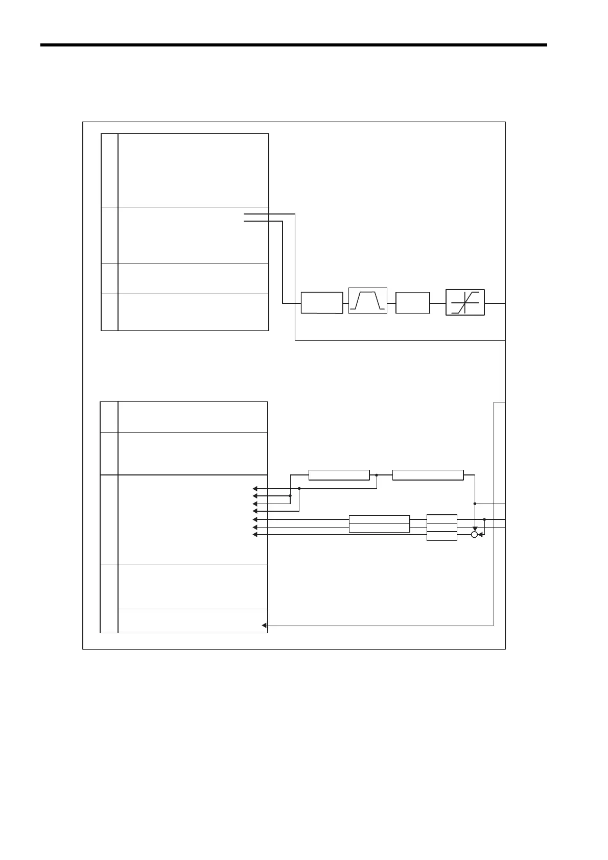
(2) Control Block Diagram for Speed Control
Acceleration: OL36
Deceleration: OL38
MP2100/MP2100M
SVB
OW00 Run Commands
Function 1OW03
OW08 Motion Command
OW09 Motion Command Options
OW0A Motion Subcommand
OL10 Speed Reference
OL14
OL18 Speed Override
OL36 Linear Acceleration Time
OL38 Linear Deceleration Time
OW3A S-Curve Acceleration Time
OL48 Zero Point Offset
OL4A Work Coordinate System Offset
OL4C Preset Data of POSMAX Turn
IW00 Drive Status
IL02 Warning
IL04 Alarm
IW08 Servo Command Type Response
IW09 Servo Module Command Status
IW0A
Motion Subcommand Response Code
IW0B Motion Subcommand Status
IW0C Position Management Status
IL0E
Machine Coordinate Target Position (TPOS)
IL10 Target Position (CPOS)
IL12
Machine Coordinate System Position (MPOS)
IL14 32-bit Coordinate System Position (DPOS)
IL16 Machine Coordinate Feedback Position (APOS)
IL18 Machine Coordinate Latch Position (LPOS)
IL1A Position Error (PERR)
IL1C Target Position Difference Monitor
IL1E POSMAX Number of Turns
IL20 Speed Reference Output Monitor
IW2C Network Servo Status
IW2D Servo Alarm Code
IW2E Network Servo I/O Monitor
IW2F
Network Servo User Monitor Information
IW30 Servo User Monitor 2
IL40 Feedback Speed
IL42 Torque (Thrust) Reference Monitor
Run Settings
Run
Information
Position InformationSERVOPACK Information
Motion Command
Information
Acceleration/
Deceleration
Coordinates Speed Reference
POSMAX processing
Follow-up processing
Electronic gear
Electronic gear
Electronic gear
−
+
Filter
OW3A
Override
Processing
Acceleration/deceleration
processing
Limiter Fixed
(No parameter)
POSMAX processing
POSMAX processing
Positive Side Limiting Torque
Setting at the Speed Reference
 Loading...


