Def / Type
FbEq 16b / 32b
DescriptionName / Range /
Selection
No.
11
Digital input/output DIO2 (11.2 DIO delayed status, bit 1).
DIO2
See Terms and abbreviations (page 132).
Other [bit]
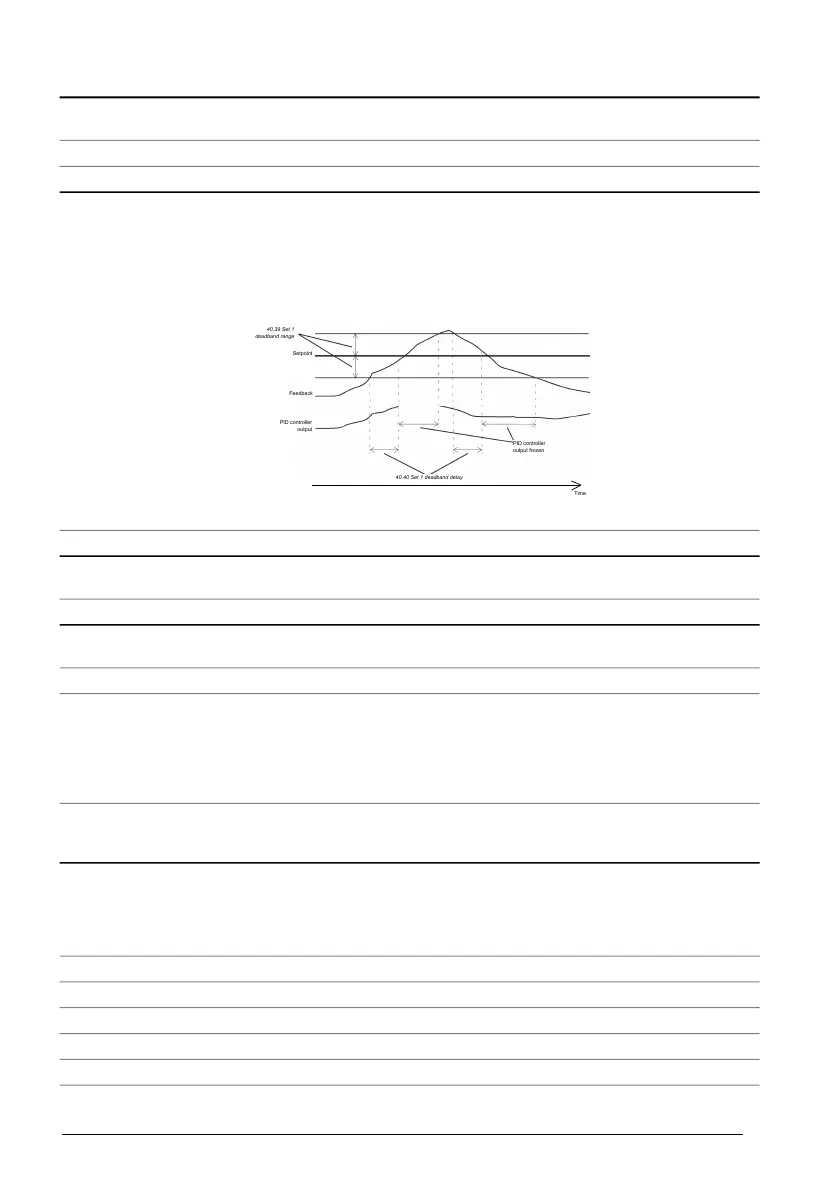
0.0 / real32Defines a deadband around the setpoint. Whenever
process feedback enters the deadband, a delay timer
starts. If the feedback remains within the deadband longer
than the delay (40.40 Set 1 deadband delay), the PID
controller output is frozen. Normal operation resumes after
the feedback value leaves the deadband.
40.39 Set 1
deadband range
40.40 Set 1 deadband delay
Setpoint
Feedback
PID controller
output
PID controller
output frozen
Time
Set 1 deadband range40.39
1 = 1 / 10 = 1Deadband range.0.0 ... 32767.0
0.0 s / real32
Delay for the deadband. See parameter 40.39 Set 1
deadband range.
Set 1 deadband delay40.40
1 = 1 s / 10 = 1 sDelay for deadband area.0.0 ... 3600.0 s
Not selected / uint16Selects the mode of the sleep function.
See also section Process PID control (page 72).
Set 1 sleep mode40.41
0Sleep function disabled.Not selected
1The output of the PID controller is compared to the value
of 40.43 Set 1 sleep level.
If the PID controller output remains below the sleep level
longer than the sleep delay (40.44 Set 1 sleep delay), the
drive enters sleep mode.
Parameters 40.44…40.48 are in force.
Internal
2The sleep function is activated by the source selected by
parameter 40.42 Set 1 sleep enable.
Parameters 40.44…40.46 and 40.48 are in force.
External
Not selected / uint32Defines a source that is used to activate the PID sleep
function when parameter 40.41 Set 1 sleep mode is set to
External.
0 = Sleep function disabled
1 = Sleep function activated
Set 1 sleep enable40.42
00Not selected
11Selected
2
Digital input DI1 (10.2 DI delayed status, bit 0).
DI1
3
Digital input DI2 (10.2 DI delayed status, bit 1).
DI2
4
Digital input DI3 (10.2 DI delayed status, bit 2).
DI3
384 Parameters