Installation
54
1SVC 440 795 M1100
The following applies to the expansion devices:
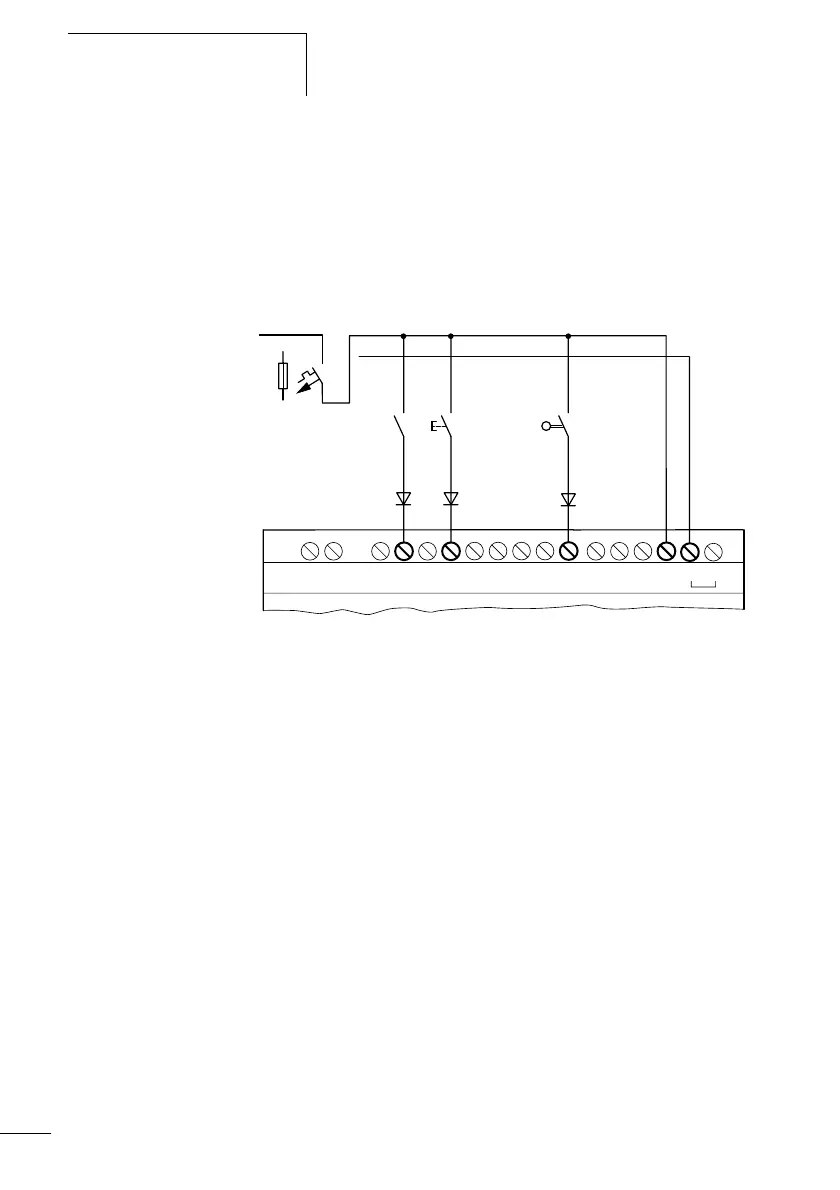
With longer cables you can connect a diode (e.g. 1N4007)
with 1 A, minimum blocking voltage in series to the input of
the expansion device. Ensure that the diode is connected in
relation to the input as shown in the circuit diagram,
otherwise the logic relay will not detect the signal 1.
Figure: 36: CL-AC2 with a diode on the inputs
Two-wire proximity switches have a residual current in the
state 0. If this residual current is too high, the logic relay
input may only detect a signal 1.
If inputs with a higher input current are required, an
additional input circuit must be used.
L1
N
R10R9R8R7R6R5R4R3R2R1E+ E–
R11
R12 NNL
115/230 V h
F1