R3132 Series Spectrum Analyzer Operation Manual
1.4.3 Power Fuse
1-8
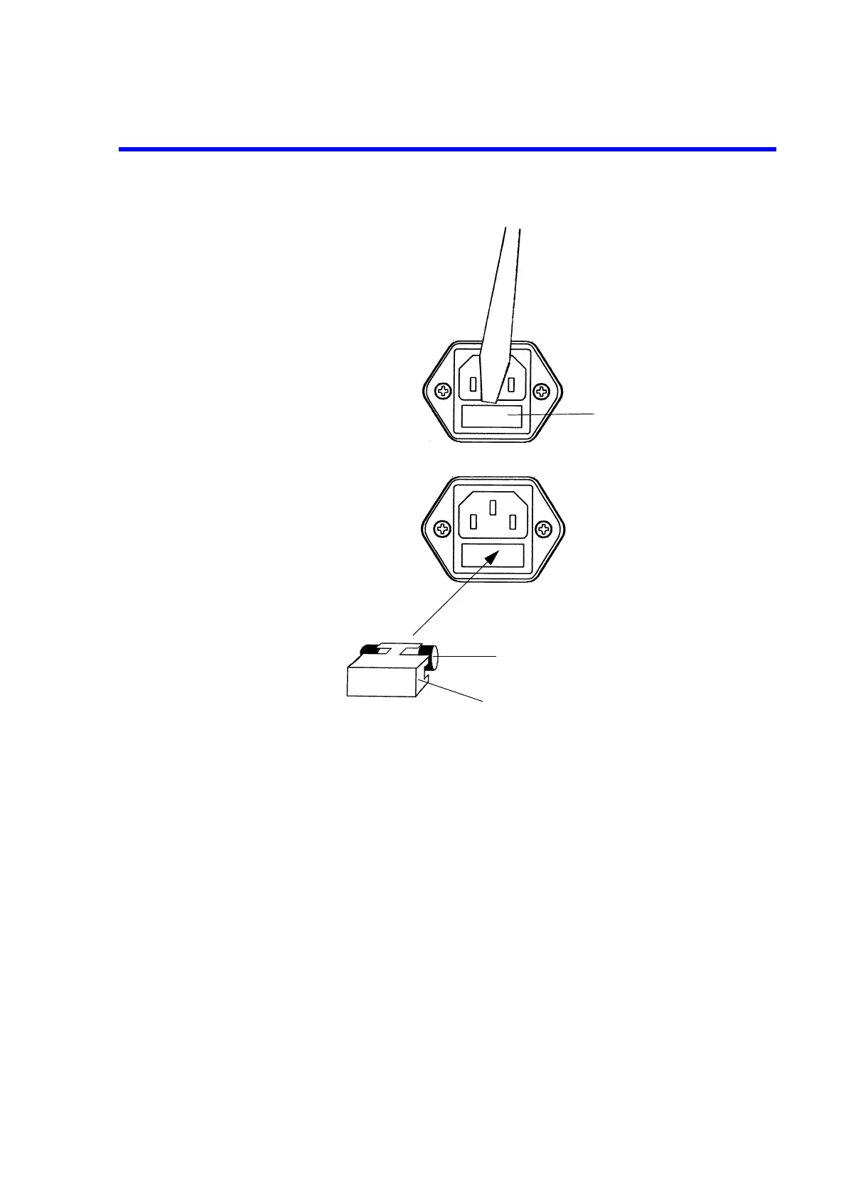
Figure 1-2 Replacing the Power Fuse
Fuse holder
Pull out the fuse holder using a slotted
head screwdriver.
Fuse (T5A/ 250V)
Check (and replace if necessary)
the power fuse and put it back into
the fuse holder.
Spare fuse attached to the fuse holder.
Fuse holder

 Loading...
