R3132 Series Spectrum Analyzer Operation Manual
5.2.10 Scale Fidelity
5-36
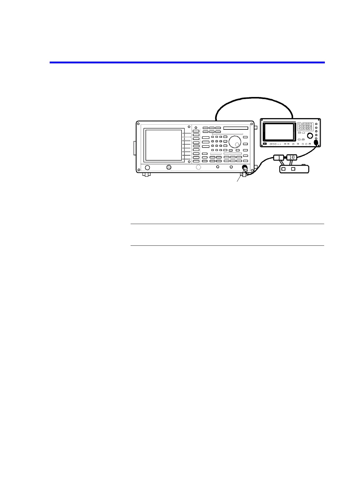
Figure 5-10 Setup of Scale Fidelity Test
CAUTION: Use only 75
Ω
ΩΩ
Ω
cables, connectors, or adapters on R3132N, or damage
to the input connector will occur.
2. On the signal generator, set controls as follows:
Frequency: 11 MHz
Output Level: 0 dBm
3. On the R3132 series, after preset, set controls as follows:
Center Frequency: 11 MHz
Frequency Span: 2 kHz
Reference Level: 0 dBm
RBW: 1 MHz
VBW: 10 Hz
dB/div: 1 dB/div
Trace Detector: Sample
4. On the 1 dB step attenuator and the 10 dB step attenuator, set the value 0 dB.
5. On the R3132 series, press PK SRCH to capture the signal peak.
6. On the signal generator, adjust the output level so that the marker reading is
0.0 dBm ± 0.01 dBm
7. On the R3132 series, press SINGLE for single sweep.
8. On the R3132 series, press as follows to set fixed marker to on.
MKR, 1/2_more, Fixed MKR ON/OFF(ON)
Minimum
Loss Pad (*1)
*1 R3132N only

 Loading...
