R3132 Series Spectrum Analyzer Operation Manual
6.4.1 External Mixer Performance Verification Test Procedures
6-57
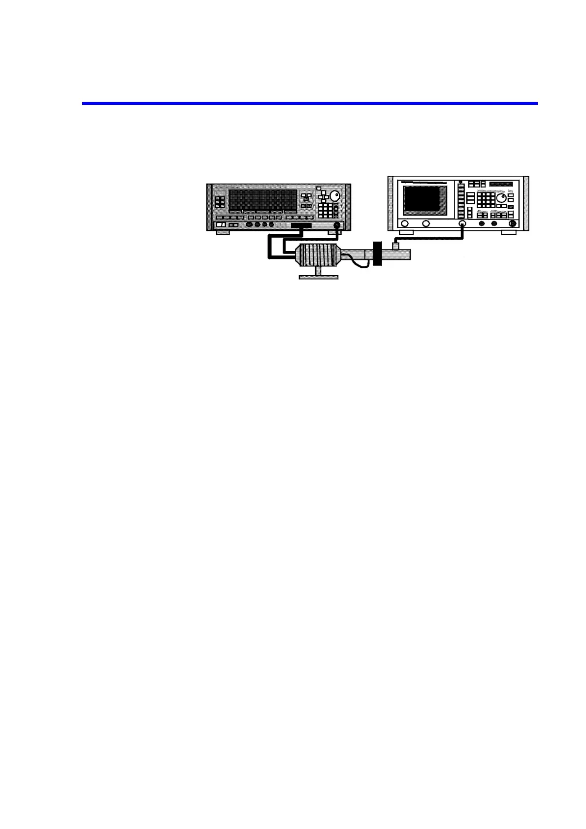
Frequency Response
Figure 6-12 Setup of Frequency Response Test
Procedure
Part 1 Source Module Calibration
1. On the RF power meter, perform ZERO and calibration with the RF power sen-
sor.
2. Connect equipment as shown in Figure 6-11.
3. On the SG, set controls as follows;
Output Frequency: 75.0 GHz
Output Level: 0 dBm
4. On the RF power meter set correction data for 75.0 GHz.
5. Measure the source module output level, and then record it in reference column
on the performance verification test record sheets.
6. On the SG, set control as follow;
Output Frequency: 75.1 GHz
7. On the RF power meter set correction data for 75.1 GHz.
8. Measure the source module output level, and then record it in reference column
on the performance verification test record sheets.
9. Repeat steps 6 through 8 for the SG output frequency and RF power meter cor-
rection data up to 110 GHz by 100 MHz steps.
Part 2 Frequency Response Test
10. Connect equipment as shown in Figure 6-11.
Sweeper (83640)
R3172/R3182
Source Module
(83558AA)
10 dB
(521W)
Ext. Mixer
(WHMB-10S)
SMA CABLE
(DCP-FF00092X02)

 Loading...
