R3132 Series Spectrum Analyzer Operation Manual
5.2.12 Noise Sidebands
5-46
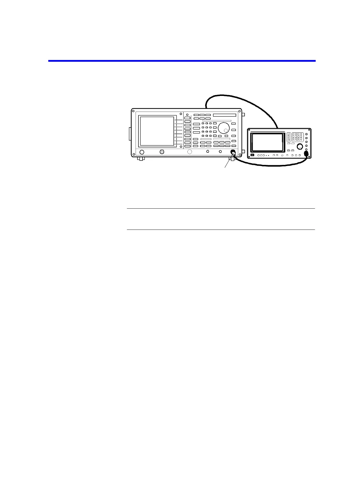
Figure 5-12 Setup of Noise Sidebands Test
CAUTION: Use only 75
Ω
ΩΩ
Ω
cables, connectors, or adapters on R3132N, or damage
to the input connector will occur.
Measuring the Noise Sidebands
2. On the signal generator, set controls as follows:
Frequency: 1 GHz
Output Level: -5 dBm
3. On the R3132 series, after preset, set controls as follows:
Center Frequency: 1 GHz
Frequency Span: 50 kHz
4. On the signal generator, press as follows to set noise marker mode to on.
PK SRCH, MKR→
→→
→, MKR
→
→→
→
Ref, PK SRCH, MEAS, Noise/Hz, dBc/Hz
5. On the R3132 series, put the noise marker at 20 kHz offset using data knob or
press 2, 0 and kHz.
6. On the R3132 series, set the reference level by 20 dB and press as follows to per-
form averaging for 20 samples.
TRACE, 1/2_more, AVG A, 2, 0, Hz(ENTER)
7. Record the level of marker reading on the performance verification record sheet.
Minimum
Loss Pad (*1)
*1 R3132N only

 Loading...
