R3132 Series Spectrum Analyzer Operation Manual
2.2.12 Intermodulation
2-46
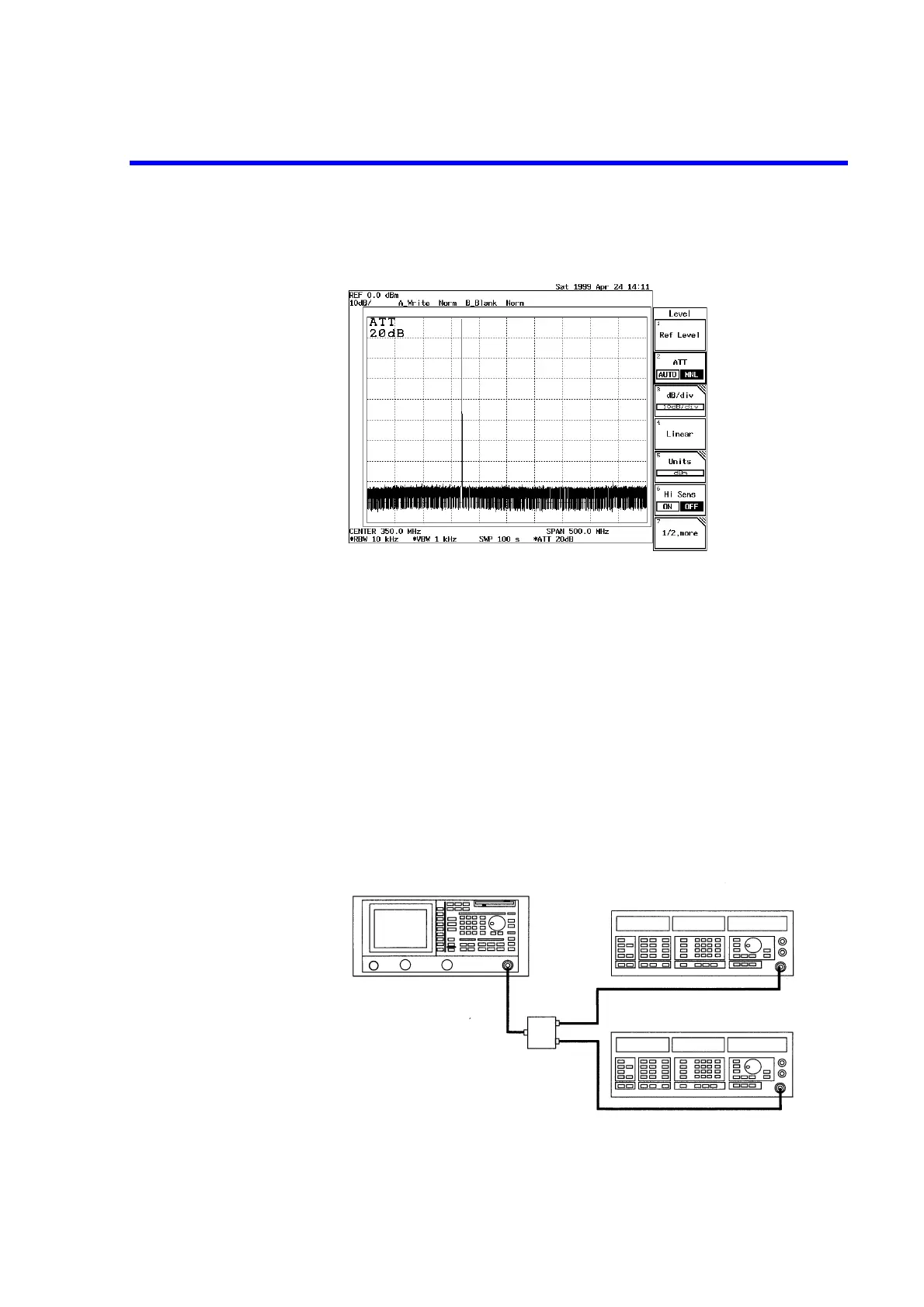
9. Press LEVEL, ATT AUTO/MNL(MNL), 2, 0 and GHz(dB).
The attenuator level is set to 20 dB.
Figure 2-38 Screen Display Showing Reduced Harmonic Distortion
The input to the mixer becomes -20 dB, and the secondary harmonic distortion gener-
ated in the spectrum analyzer decreases by 10 dB.
2.2.12 Intermodulation
This section describes how to set up the attenuator (ATT) when using a spectrum analyzer which is receiv-
ing more than one input signal.
When signals with an excess amplitude are input, spurious signals produced by intermodulation are dis-
played. It is important that the ATT be adjusted to moderate the mixer input.
Setup
1. Connect the signal generators as shown in Figure 2-39.
Figure 2-39 Setup for Measuring Intermodulation
Signal generator (SG1)
Signal generator (SG2)
Power combiner
(Insertion loss: 6 dB)
OUTPUT
connector
OUTPUT
connector
RF INPUT 1
connector
R3132 Series Spectrum analyzer

 Loading...
