R3132 Series Spectrum Analyzer Operation Manual
2.1.3 Rear Panel
2-14
2.1.3 Rear Panel
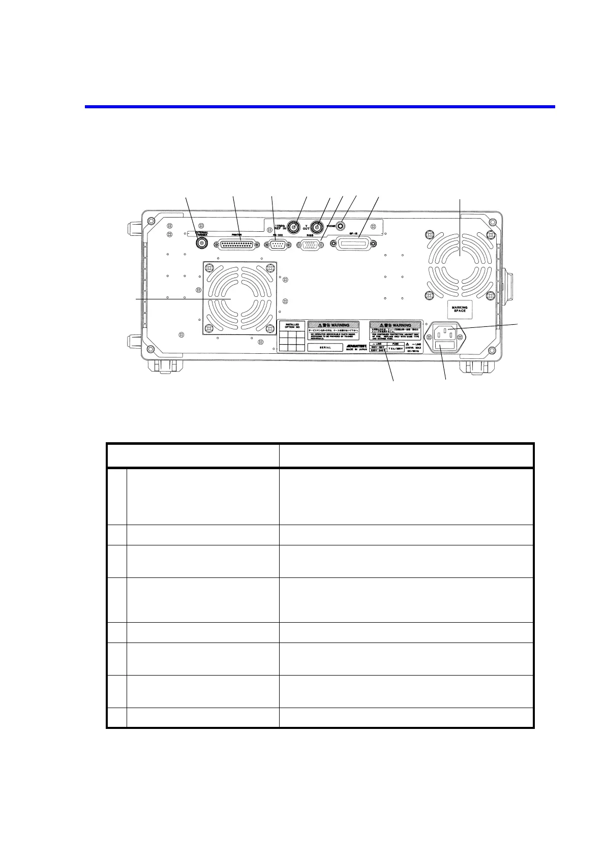
This subsection shows the rear panel and describes its terminals and connectors.
Figure 2-5 Rear Panel
Control Description
1 EXTERNAL TRIGGER
terminal
The input impedance is approximately 10 kΩ.
The R3132 and R3162 start sweeping frequencies when the
input signal rises or trails. (The timing is selectable.)
This signal can be used as the gated sweep signal source.
2 PRINTER connector Connector used when attaching a Centronix printer
3 RS-232 connector Connector for an external unit used to control the spectrum
analyzer through an RS-232 interface
4 10 MHz REFERENCE INPUT
terminal
Input terminal for 10 MHz reference frequency signal
Input impedance: Approximately 500 Ω
Input level: -10 dBm to +10 dBm
5 Y-OUT terminal 10 dB/div Y signal output
6 RGB connector Connector for an external monitor compatible with VGA
specifications.
7 PHONE connector Connector for an 8 Ω earphone used for AM/FM demodu-
lated audio output
8 GPIB connector Connector for an external controller cable
123458 9
10
11
12
7
9
6

 Loading...
