R3132 Series Spectrum Analyzer Operation Manual
2.1.1 Front Panel
2-4
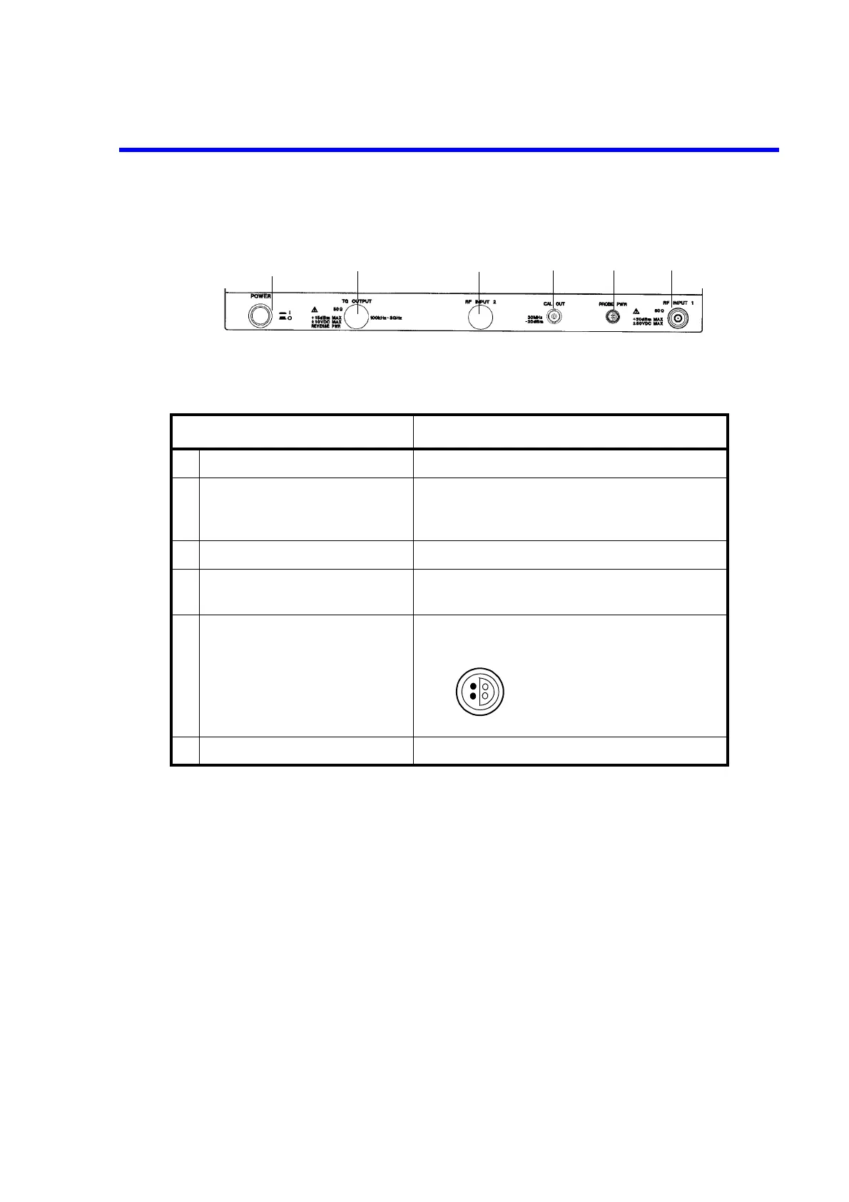
(2) Power Switch/Connector Section
• R3132/32N/62
Control Description
1
POWER
switch Turns the power on or off
2
TG OUTPUT
connector (Option)
TG output connector
Frequency range is 100 kHz to 3 GHz
3
RF INPUT 2
connector (Unused)
4
CAL OUT
connector Calibration signal output connector
30 MHz, -20 dBm
5
PROBE PWR
connector Power output for the accessory.
The maximum current is 100 mA
6
RF INPUT 1
connector Inputs the signal to be measured.
1
3
2
4
5
6
32
41
1: NC
2: GND
3: -12V
4: +12V

 Loading...
