R3132 Series Spectrum Analyzer Operation Manual
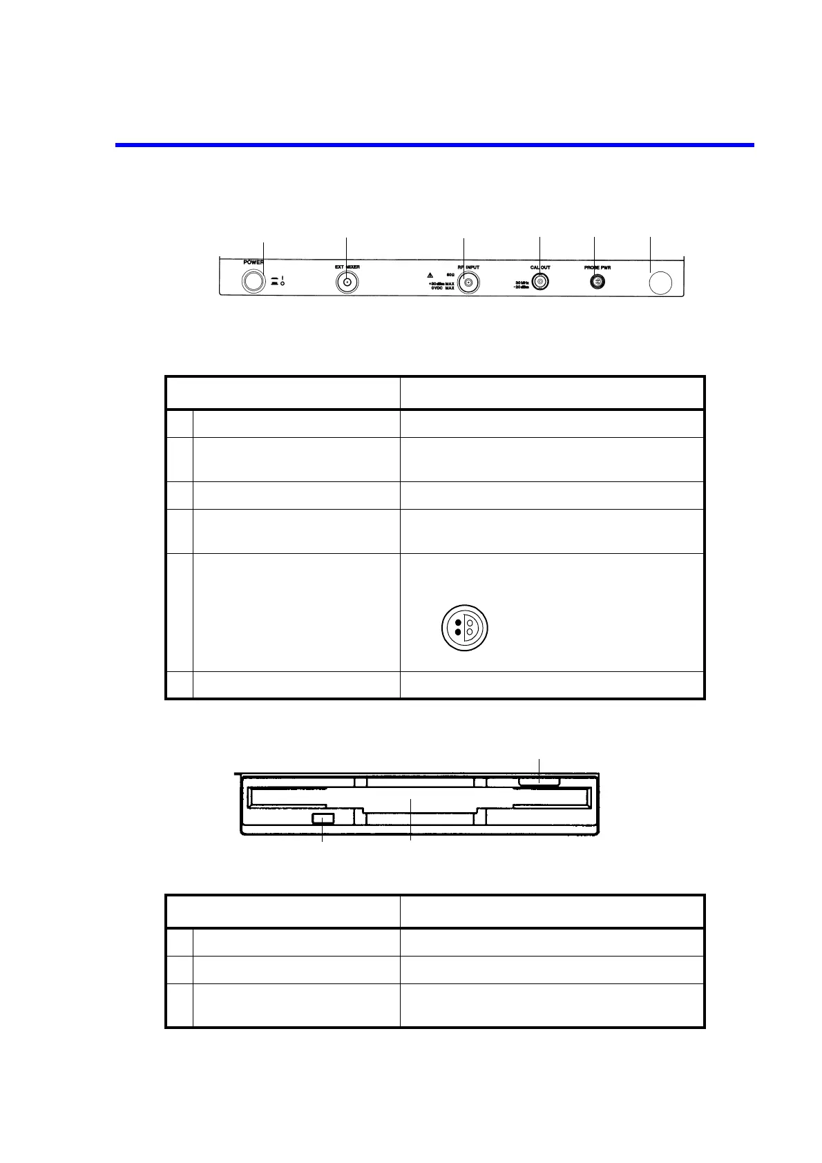
2.1.1 Front Panel
2-6
• R3182
(3) Floppy Disk Drive Section
Control Description
1
POWER
switch Turns the power on or off
2
EXT MIXER
connector Connects an external mixer to increase the measure-
ment frequency range.
3
RF INPUT
connector Inputs the measurement signal.
4
CAL OUT
connector Calibration signal output connector
30 MHz, -20 dBm
5
PROBE PWR
connector Power output for the accessory.
The maximum current is 100 mA
6 (Unused)
Control Description
1 Eject button Used to eject floppy disks from the drive
2 Floppy disk drive door Insert floppy disks here
3 Access lamp Turns on when the floppy disk in the drive is being
accessed
1
3
2
4
5
6
32
41
1: NC
2: GND
3: -12V
4: +12V
1
2
3

 Loading...
