92
6. Alarm and troubleshooting
WARNING: Person without maintaining experience mustn’t mend the machine.
CAUTION: If alarm occurs, the patient’s safety must be protected firstly, then do
troubleshooting or necessary remedy.
CAUTION: Alarm presets will change with patient type automatically.
CAUTION: When several alarms occur at the same time, alarm message only displays
the front two in a sequence of “High” to “Low”.
CAUTION: When alarm silencing, the alarm bell has dashed “X” on itself. After
120s, the alarm bell renews to the old state; if the alarm is not dealt in time, alarm
continues.
CAUTION: If alarm occurs when the anaesthetic machine works normally, visible and
audible signals will delay a certain time.
WARNING: Do not set alarm limit exceeding the extremes, otherwise, alarm system will
failure.
WARNING: A potential hazard can exist if different alarm presets are used for the same
or similar equipment in any single area, such as ICU or cardio tic operating room.
WARNING: The operator should examine if the current alarm setting is suitable for
every patient.
WARNING: When power supply is interrupted, system will still renew the last alarm
settings when opening again.
6.1. Brief introduction of alarm message
There are three priorities for alarm status: high priority, medium priority, and low priority.
High-priority alarms need to be handled immediately.
The operator can judge whether the alarm system is working through visual alarm signals and
auditory alarm signals. The operator of the Anaesthesia workstation shall accurately detect the
visual alarm signal at 4m, and this visual indication is on the display screen. The sound pressure
level of the alarm signal shall not be lower than 60dB at the position of 1m on the horizontal plane
of the geometric center in front of the equipment.
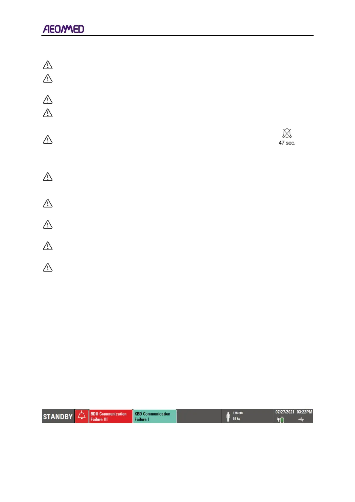
The alarm information is displayed in the middle area at the top of the user interface, as shown in
the figure below.
The top area of the user interface displays alarm message, see figure 6-1.
Table 6-1 alarm bar