8210-00020 R1 127
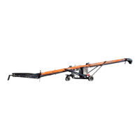
3.34. Assemble the A-Frame
Ensure the wheels are mounted to the axle before beginning this procedure.
1. Loosely fasten the axle arms (7) to the axle (4) using one 5/8" x 5" bolt (11), three 5/8" x 2" bolts (8), five
5/8" flat washers (9), and four 5/8" nylon locknuts (10).
Note
The axle arms will be tightened after the upright arms have been installed.
2. Fasten the axle arms to the suspension bracket using 3/4" x 2" hex bolts (12) and 3/4" nylon locknuts (14).
3. Secure the slider (2) to the end of the track (towards the spout) using vise-grips.
4. Fasten upright arms (1) to the slider (2) using 1/4" x 2" cotter pins (3) and 3/4" flat washers (13).
5. Lift the spout end of the tube until the loose ends of the upright arms align with their brackets on the axle.
6. Fasten the upright arms (1) to the axle (4) using 1" x 3" hex bolts (5) and 1" nylon locknuts (6).
7. Tighten the bolts that fasten the axle arms to the axle.
8. Lower tube and remove vise grips.
Do not remove the tube support(s) until the conveyor is fully assembled.
Table 25. Components to Assemble the A-Frame
Item
Description
1
Upright Arm
2
Slider
3
1/4" x 2" Cotter Pin
4
Axle
5
1" x 3" Hex Bolt (GR8)
6
1" Nylon Locknut (GR8)
7
Axle Arm
8
5/8" x 2" Hex Bolt (GR8)
9
5/8" Flat Washer
10
5/8" Nylon Locknut (GR8)
11
5/8" x 5" Hex Bolt (GR8)
12
3/4" x 2" Hex Bolt (GR8)
13
3/4" Flat Washer
14
3/4 " Nylon Locknut (GR8)
Hardware Kit: HRDW-15-31, HRDW-15-123
FIELD LOADER S-DRIVE – PORTABLE GRAIN BELT CONVEYOR 3. ASSEMBLY