24 8210-00020 R1
3.7. Assemble the Conveyor Tube
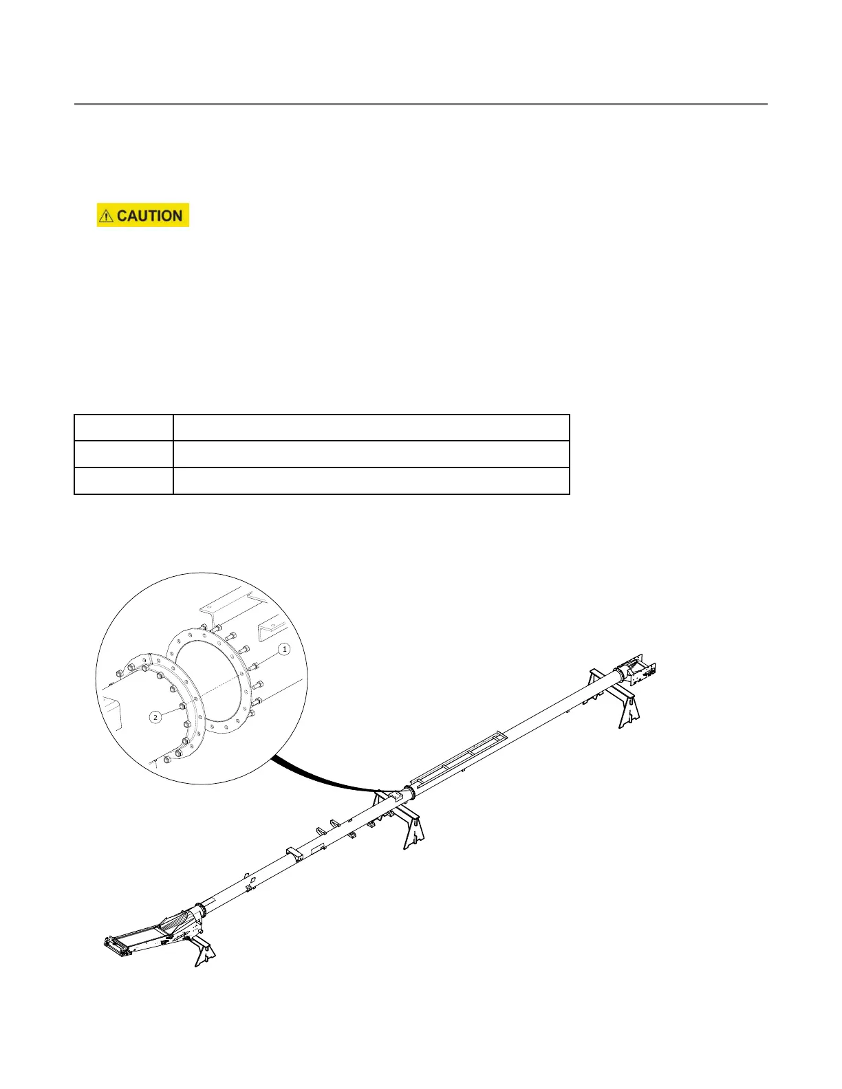
1. Review the tube layout figure below for your specific conveyor model to determine the order in which the
tubes must be connected together. Part numbers are shown for tube identification.
2. Place the tubes on two support stands to support each tube section. The support stands must be set at
equal height (see Figure 8). Anchor the tubes to the stands if necessary to prevent rolling.
Failure to secure the tubes may result in personal injury.
3. Confirm that all tubes are set level and oriented correctly.
4. Fasten tube flanges together with 7/16" x 1" bolts (1) and 7/16" locknuts (2) as each tube section is placed,
starting at the hopper end and working toward the spout end. Ensure the tubes are aligned and the bolts
are straight.
Note
A punch can be used to assist alignment. If you are not careful, it is possible to bolt the flanges
together non-concentrically with the bolts crooked through the holes.
Table 3. Tube Connection Components
Item
Description
1
7/16" x 1" Hex Bolt UNC GR8 ZN
2
7/16" Locknut UNC GR8 ZN
Hardware Kit: HRDW-15-07
Figure 8. Typical Tube Connection
3. ASSEMBLY FIELD LOADER S-DRIVE – PORTABLE GRAIN BELT CONVEYOR