8210-00020 R1 23
3.6. Assemble the Remainder of the S-Drive
Note
The s-drive normally comes mostly pre-assembled when delivered from the factory. The steps below are
the remaining assembly which must be performed.
For each side of the s-drive:
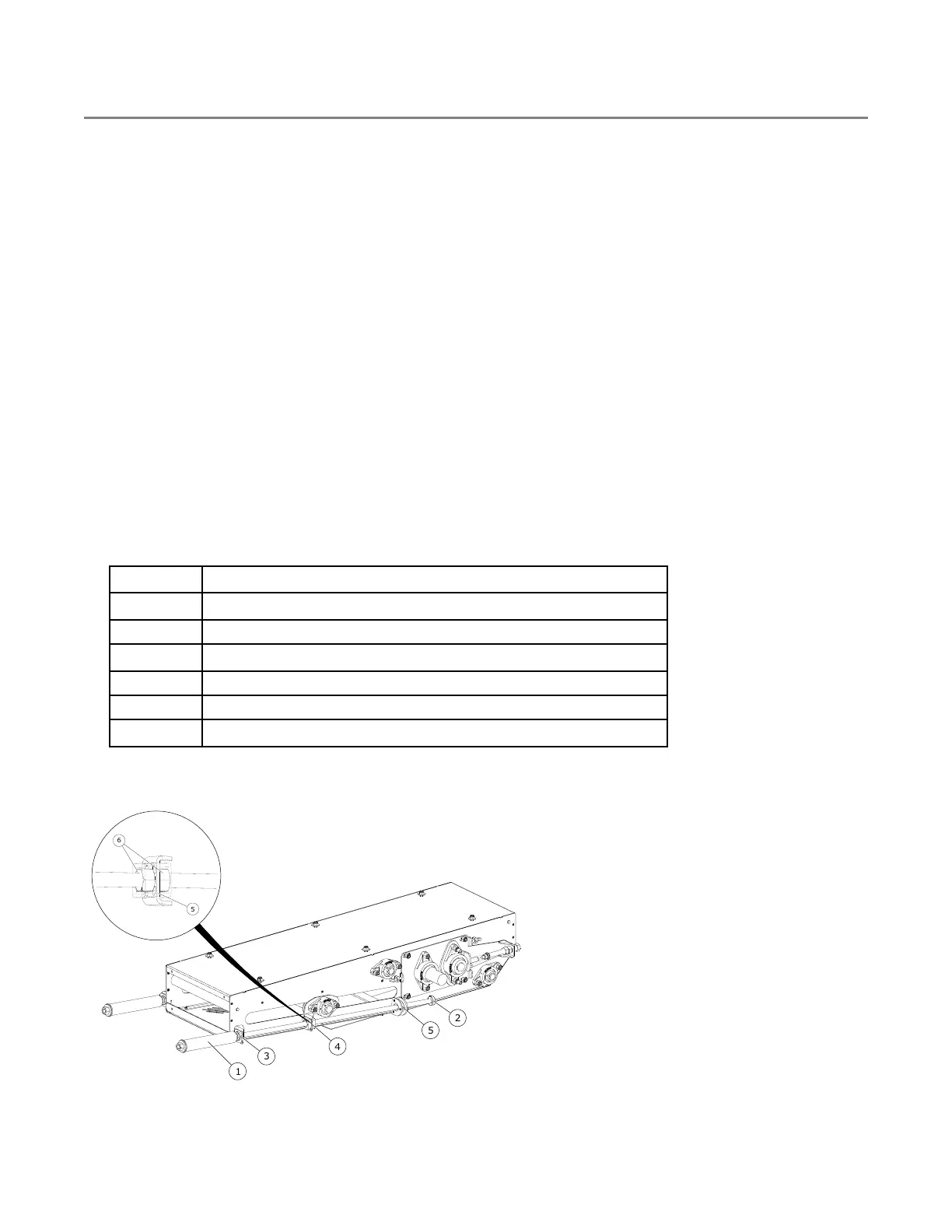
1. Remove the lock collar (2) and hex nuts (6) from the pretensioner assembly.
Note
The pretensioner assembly (1) is comprised of the threaded rod weldment, pretensioner pipe,
spring, lock collar, and two hex nuts. This is factory pre-assembled.
2. Position a hex nut (6) on each side of the slider weldment.
3. Thread the pretensioner assembly (1) through the spring capture plate (3), hex nuts in the slider weldment
(4), and roller in the bolt on pretensioner tab (5).
4. Re-fasten the lock collar (2).
Note
The s-drive bottom guard and take-up bolt guard will be assembled onto the conveyor later, after
belt tensioning and alignment. See Section 3.25 – Attach the S-Drive Bottom and Take-up Side
Guards on page 113.
Table 2. Installing the Take-up Roller Bolt Assembly
Item
Description
1
Pretensioner Assembly
2
Lock Collar
3
Spring Capture Plate
4
Slider Weldment
5
Pretensioner Tab
6
3/4" Hex Nut UNC GR8 ZN
Figure 7. Installing the Take-up Roller Bolt Assembly
FIELD LOADER S-DRIVE – PORTABLE GRAIN BELT CONVEYOR 3. ASSEMBLY