Mag Err and Phase Err are especially useful to determine if your signal
contains AM, PM, spurious, or excessive noise errors. AM errors increase
Mag Err; PM errors increase Phase Err; spurious and noise errors increase
both Mag Err and Phase Err.
The EDGE demodulation format adds two new error parameters to the
symbol table: pk EVM and 95% EVM. pk EVM is the mean (average) of
the peak EVMs—one per measurement (it is a mean of the peaks, not a
peak of the peaks). 95% EVM is the error-vector-magnitude (EVM) below
which 95% of the individual symbol EVM’s occur.
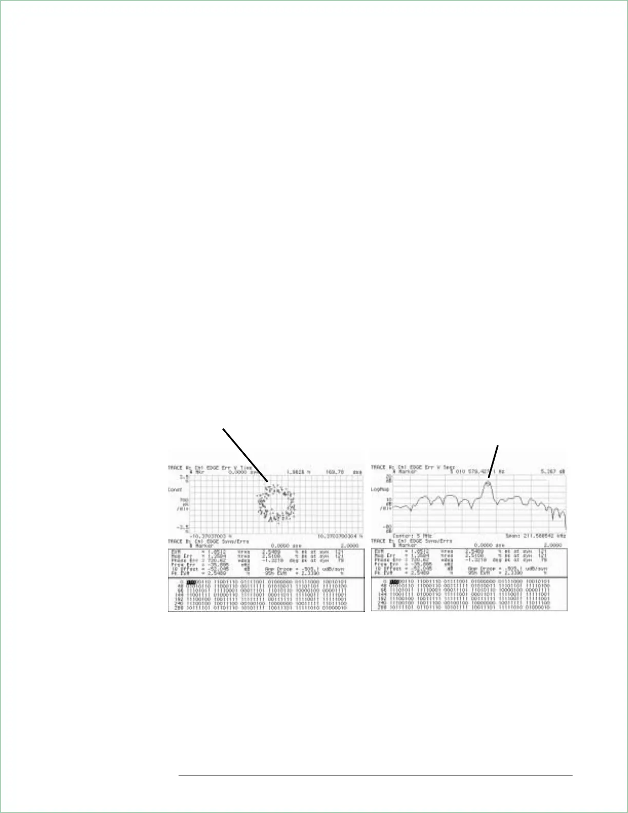
The error-vector trace shows the error vector between the measured signal
(IQ measured) and the ideal signal (IQ reference) at the symbol locations.
The error-vector vector diagram shows the magnitude and phase errors at
the symbol locations. The error-vector spectrum shows undesired spectral
components at the symbol locations.
Two 2-grid displays. The first display shows the vector diagram of the error-vector
trace and the symbol table in the lower grid. The second display shows the
spectrum of the error-vector trace and the symbol table in the lower grid.
The error-vector vector diagram is a good
troubleshooting tool for EDGE signals. Here, the
error-vector vector diagram shows the effect of the
spur added to our EDGE signal—equal amplitude and
phase errors.
The 5.01 MHz spur is clearly seen
in the error-vector spectrum trace.
Using Digital Demodulation (Opt. AYA)
8 - 13
 Loading...


