Each point in the impulse-response display corresponds to a tap in the
feed-forward equalizer (FFE). In a FFE, large coefficients that are
separate from the main tap correspond directly to alternate signal paths.
The smaller peaks are a result of the same alternate signal paths that
created the large peaks. In other words, a signal with one strong alternate
path will have more than two impulses on the display (the main impulse
and the impulses due to the alternate path). The additional impulses will
be lower than the two main impulses.
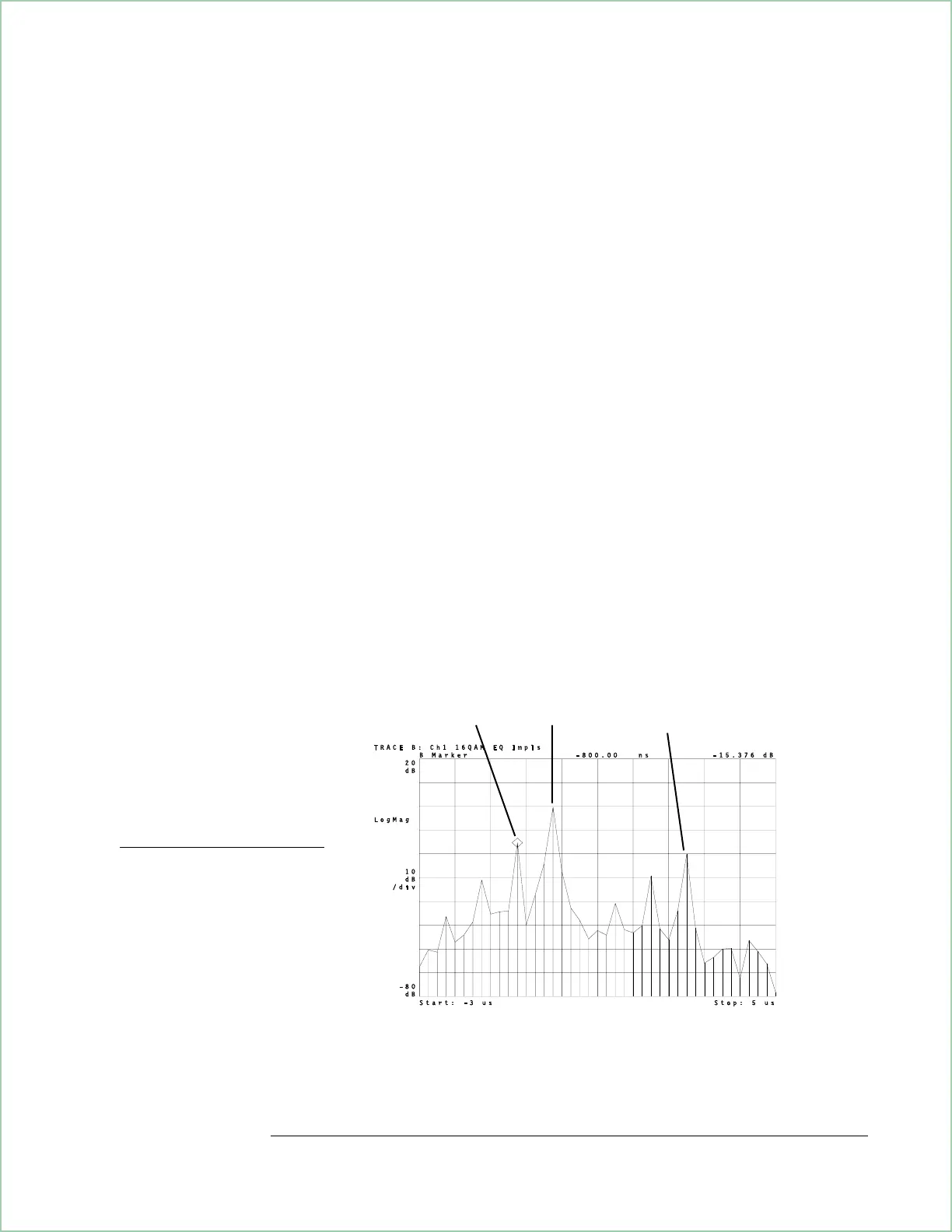
Using the impulse-response display to measure multi-path signals.
In this example, the signal has
3 paths. The strongest path
is not the shortest path. The
shortest path passed through
a building causing it to be
attenuated. Normally, the
strongest path will be the
shortest, or direct path.
Path 2
Path 3
Path 1
Using Adaptive Equalization (Options AYA and AYH)
12-9
 Loading...


