VPLS Features
Page 356 7750 SR OS Services Guide
SDP Statistics for VPLS and VLL Services
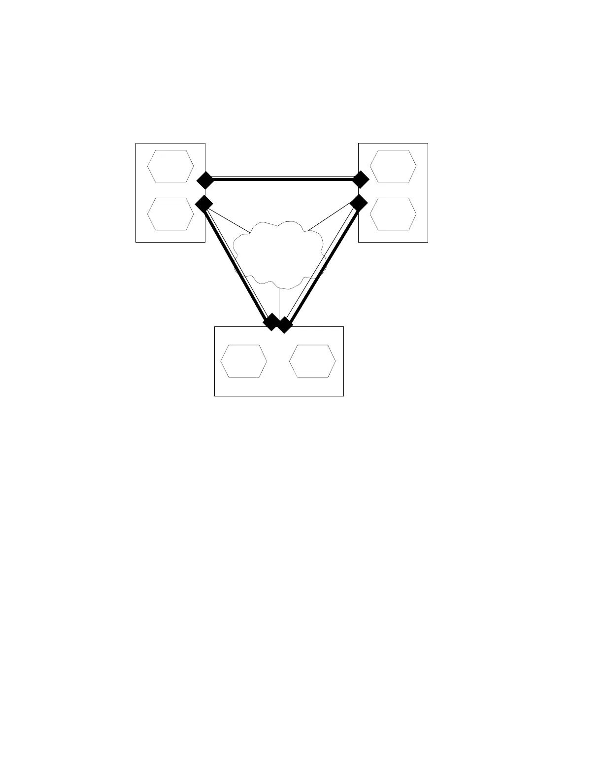
Figure 10: SDP Statistics for VPLS and VLL Services
The simple three-node network described in Figure 42 shows two MPLS SDPs and one GRE SDP
defined between the nodes. These SDPs connect VPLS1 and VPLS2 instances that are defined in
the three nodes. With this feature the operator will have local CLI based as well as SNMP based
statistics collection for each VC used in the SDPs. This will allow for traffic management of tunnel
usage by the different services and with aggregation the total tunnel usage.
SDP statistics allow providers to bill customers on a per-SDP per-byte basis. This destination-
based billing model is can be used by providers with a variety of circuit types and have different
costs associated with the circuits. An accounting file allows the collection of statistics in a bulk
manner.
VPLS1
VPLS2
VPLS1
VPLS2
VPLS2
VPLS1
IP/MPLS
PE1
PE3
PE2
SDP 101
SDP 102
GRE
RSVP
SDP 103
LDP