Prerequisites
1. Follow the procedure in Before working inside your computer.
2. Remove the left cover.
3. Remove the right cover.
4. Remove the top fan filter.
5. Remove the top cover.
6. Remove the front fan filter.
About this task
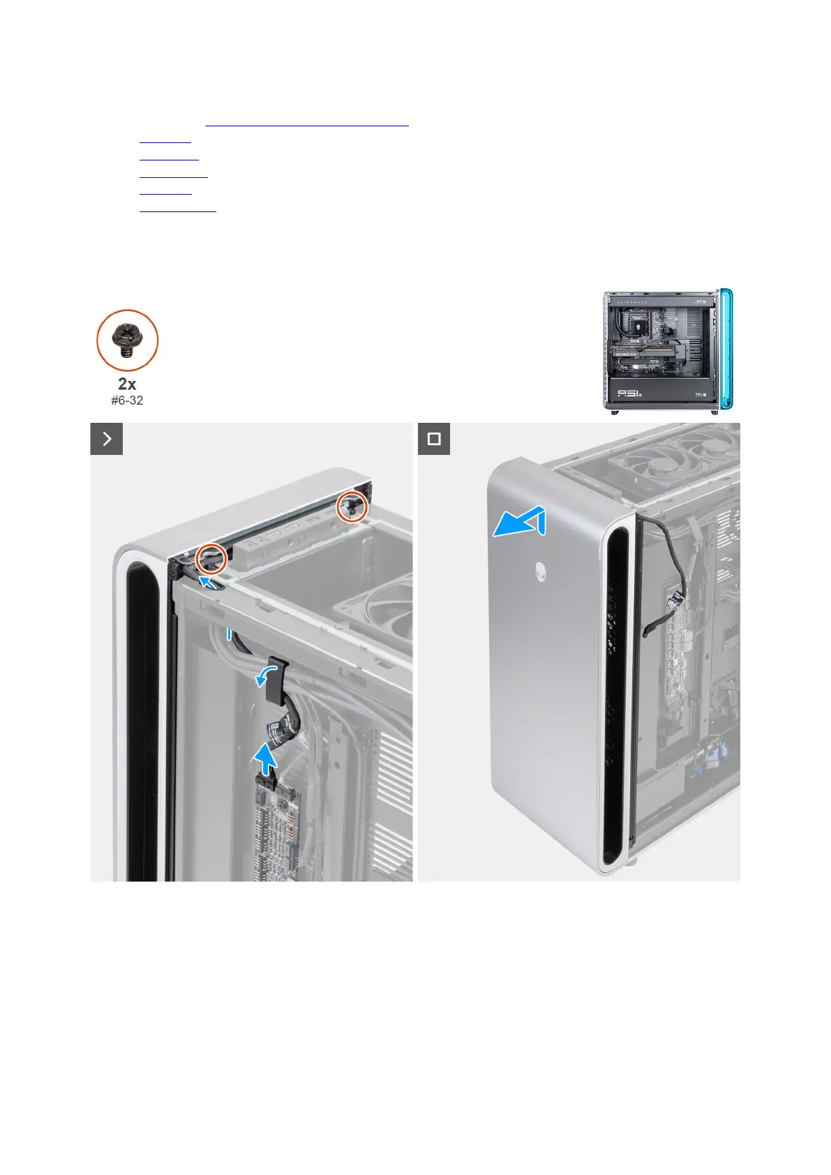
The following images indicate the location of the front bezel and provide a visual representation of the removal procedure.
Figure 90. Removing the front bezel
Steps
1. Disconnect the power button LED cable from the LED connector (RING_AMBIENT_PWBT) on the AlienFX board.
2. Unlock the securing clip and remove the power button LED cable from the securing clip and route the cable through opening at
the top of the chassis.
3. Remove the two screws (#6-32) that secure the front bezel to the chassis.
4. Slide and lift the front bezel, along with the power button LED cable, away from the chassis.
104 Removing and installing Field Replaceable Units (FRUs)