2. 12-pin + 4-pin connector for the graphics card
3. 8-pin connector for the processor
4. 4-pin connector for the processor
5. 6-pin connector for AUX
6. 10-pin connector for the system board
7. 8-pin connector for DATA
AlienFX board
Removing the AlienFX board
Prerequisites
1. Follow the procedure in Before working inside your computer.
2. Remove the right cover.
About this task
NOTE: The service warranty for the AlienFX board is valid only if it is used with the system board that comes with the factory
shipment. Dell does not offer technical support for system boards that are purchased outside of Dell.
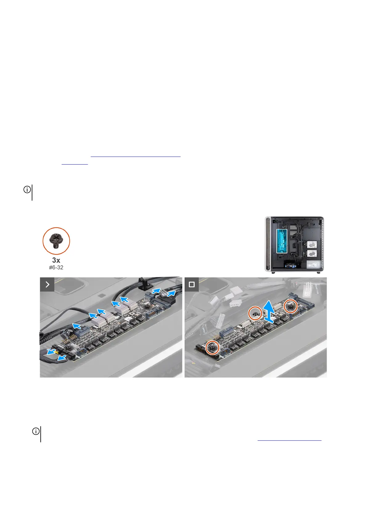
The following images indicate the location of the AlienFX board and provide a visual representation of the removal procedure.
Figure 78. Removing the AlienFX board
Steps
1. Lay the computer on the left side.
2. Disconnect all the cables from the AlienFX board.
NOTE: Note the connection and routing of the cables as you remove them so that you can connect them correctly when
replacing the AlienFX board. For more information about AlienFX-board connectors, see AlienFX-board connectors.
3. Remove the three screws (#6-32) that secure the AlienFX board to the chassis.
4. Lift the AlienFX board off the chassis.
Removing and installing Customer Replaceable Units (CRUs) 91