5. Remove the USB cables through the opening on the chassis.
6. Remove the audio cable through the opening on the chassis.
7. Lay the computer in the upright position.
8. Unlock the securing clips and remove the USB cables from the securing clips.
9. Remove the audio cable out of the securing clips on the chassis.
10.Remove the screw (#6-32) that secures the top I/O-panel to the chassis.
11. Slide and remove the top I/O-panel, along with the cables, through the opening on the chassis.
Installing the top I/O-panel
CAUTION: The information in this installation section is intended for authorized service technicians only.
Prerequisites
If you are replacing a component, remove the existing component before performing the installation procedure.
About this task
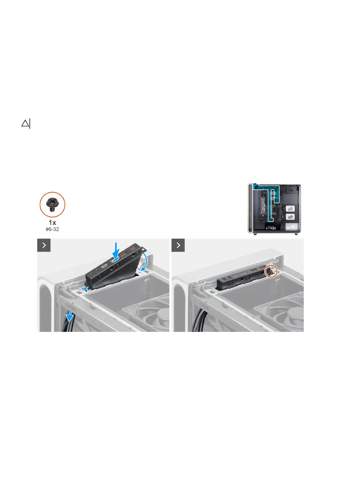
The following images indicate the location of the top I/O-panel and provide a visual representation of the installation procedure.
Figure 88. Installing the top I/O-panel
102 Removing and installing Field Replaceable Units (FRUs)