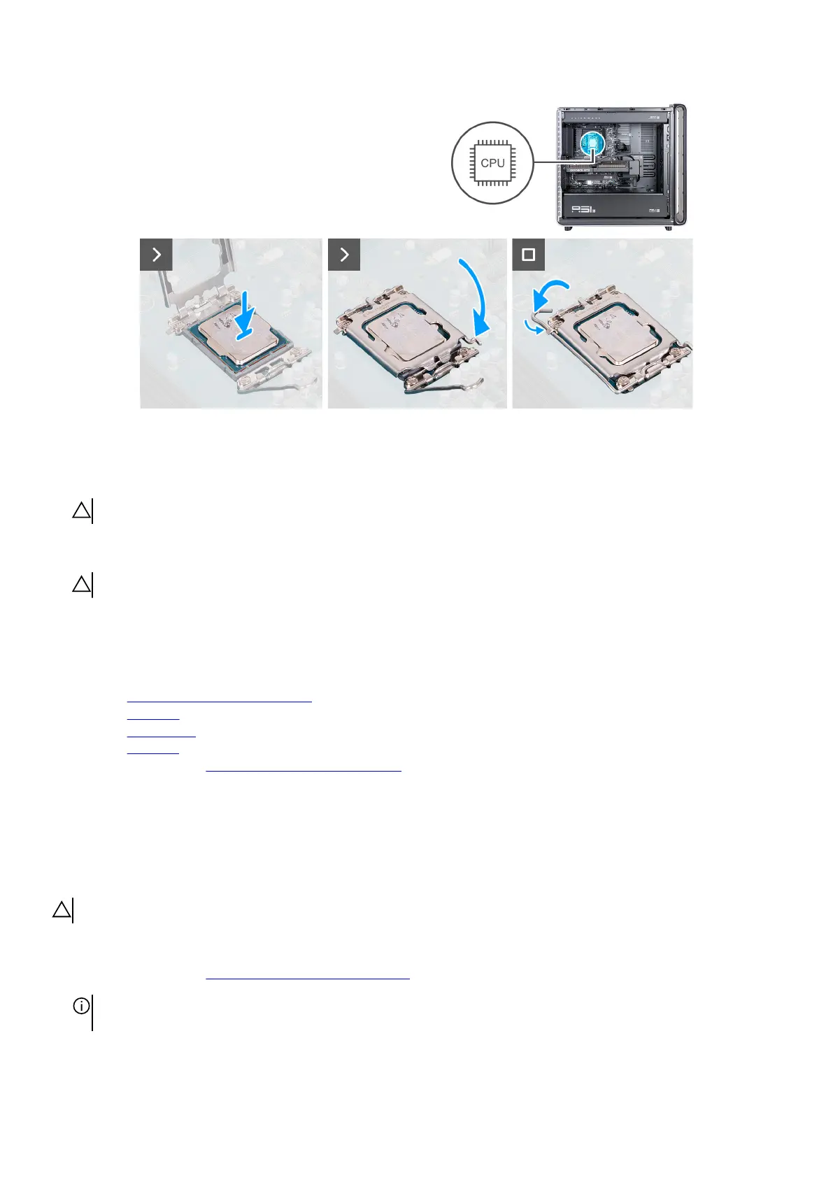
Figure 119. Installing the processor
Steps
1. Ensure that the release lever on the processor socket is fully extended and the processor cover is fully open.
CAUTION: Position the processor correctly in the processor socket to avoid permanent damage to the processor.
2. Align the pin-1 corner on the processor with the pin-1 corner on the processor socket, and then place the processor in the
processor socket.
CAUTION: Ensure that the processor-cover notch is positioned underneath the alignment post.
3. When the processor is fully seated in the socket, close the processor cover.
4. Push the release lever down and place it under the tab on the processor cover.
Next steps
1. Install the processor liquid-cooling assembly.
2. Install the top cover.
3. Install the top fan filter.
4. Install the left cover.
5. Follow the procedure in After working inside your computer.
System board
Removing the system board
CAUTION: The information in this removal section is intended for authorized service technicians only.
Prerequisites
1. Follow the procedure in Before working inside your computer.
NOTE: Your computer’s Service Tag is stored in the system board. You must enter the Service Tag in the BIOS setup program
after you replace the system board.
132 Removing and installing Field Replaceable Units (FRUs)





 To Next Page