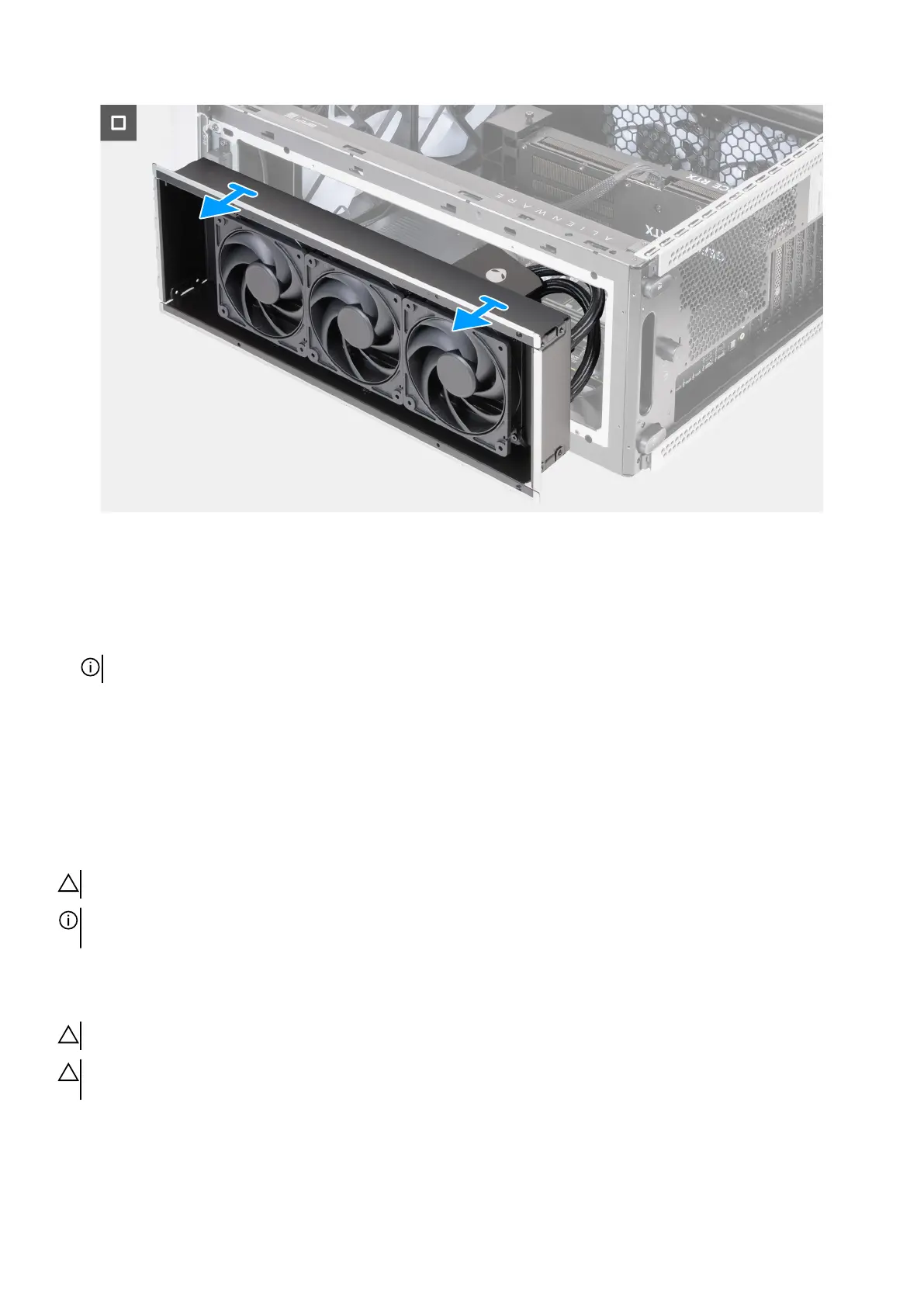
Figure 97. Removing the processor liquid-cooling assembly
Steps
1. Lay the computer on the right side.
2. Remove the four screws (M3x5) that secures the top fan assembly to the chassis.
3. Disconnect the top fan assembly cables from the fan connectors (FAN1, FAN2, and FAN3) on the system board.
NOTE: Depending on the configuration ordered, the number of fan connectors may vary.
4. Remove the top fan assembly cables from the securing clip on the chassis.
5. Disconnect the processor liquid-cooling assembly cables from the connectors (LED PUMP and PWR PUMP) on the system board.
6. In the reverse sequential order, loosen the four captive screws that secure the processor liquid-cooling assembly to the system
board.
7. Remove the top-fan assembly, along with the processor liquid-cooling assembly and cables, out of the chassis.
Installing the processor liquid-cooling assembly
CAUTION: The information in this installation section is intended for authorized service technicians only.
NOTE: Depending on the configuration ordered, your computer is shipped either with a 240 mm or a 360 mm processor
liquid-cooling assembly.
Prerequisites
If you are replacing a component, remove the existing component before performing the installation procedure.
CAUTION: Incorrect alignment of the processor liquid-cooling assembly can damage the system board and processor.
CAUTION: If either the processor or the heat sink is replaced, use the thermal grease that is provided in the kit to ensure
that thermal conductivity is achieved.
About this task
The following images indicate the location of the processor liquid-cooling assembly and provide a visual representation of the
installation procedure.
Removing and installing Field Replaceable Units (FRUs) 111