Installing the front bezel
CAUTION: The information in this installation section is intended for authorized service technicians only.
Prerequisites
If you are replacing a component, remove the existing component before performing the installation procedure.
About this task
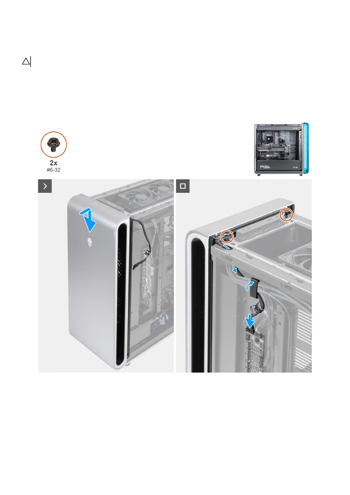
The following images indicate the location of the front bezel and provide a visual representation of the installation procedure.
Figure 91. Removing the front bezel
Steps
1. Using the alignment post at the bottom, align and place the front bezel on the chassis.
2. Push the front bezel towards the chassis and ensure the tabs clip onto the slots of the chassis.
3. Route the power button LED cable through the opening on the chassis.
4. Insert the power button LED cable into the securing clip and lock the securing clip to secure the power button LED cable.
5. Connect the power button LED cable to the LED connector (RING_AMBIENT_PWBT) on the AlienFX board.
Removing and installing Field Replaceable Units (FRUs) 105