Installation
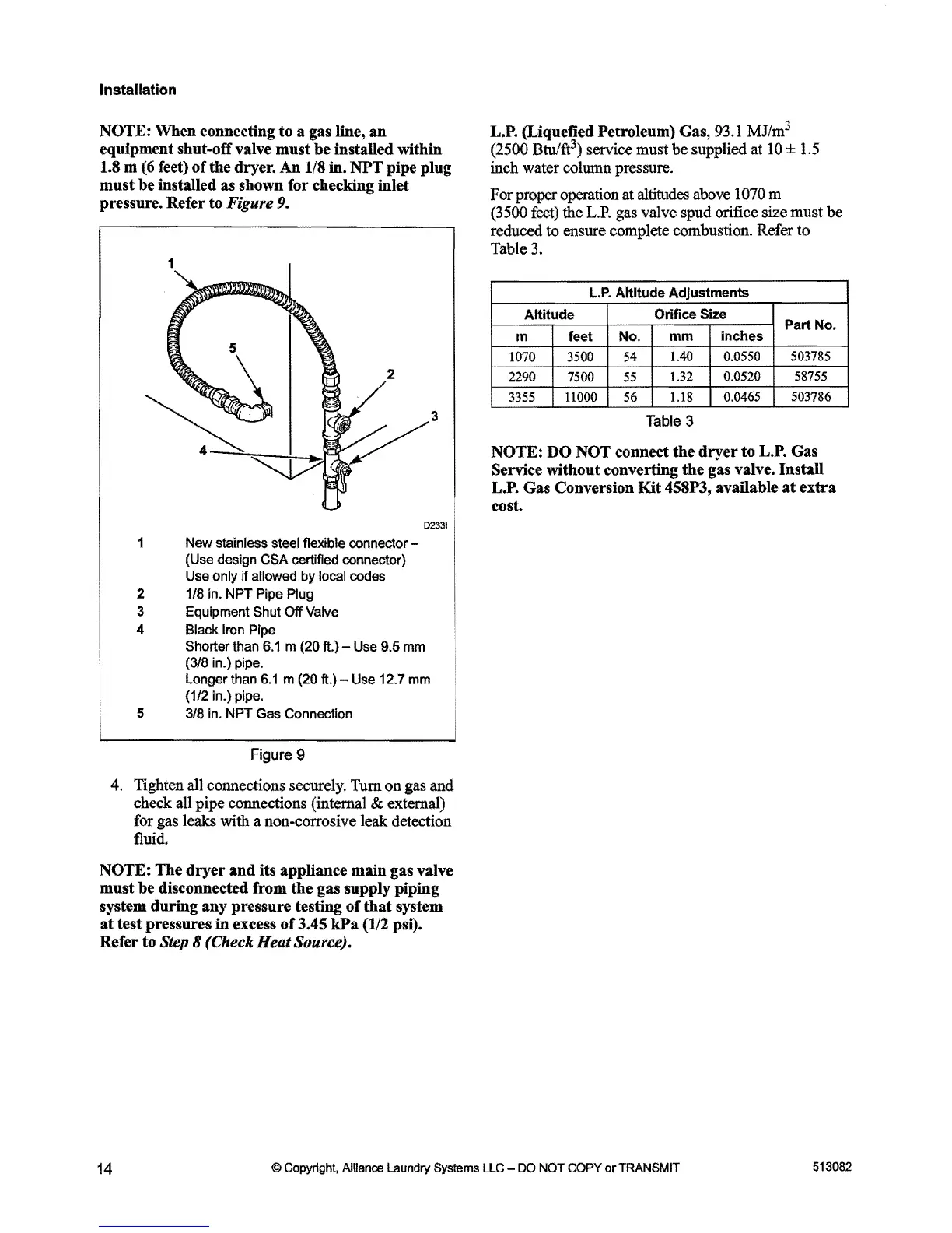
NOTE: When connecting
to
a gas line,
an
equipment shut-off valve
must
be
installed within
1.S m
(6
feet)
of
the dryer.
An
l/S
in.
NPT
pipe plug
must
be
installed as shown for checking inlet
pressure. Refer to
Figure 9.
1
2
1
2
3
4
5
New stainless steel flexible connector -
(Use design CSA certified connector)
Use only
jf
allowed by local codes
1/8 in. NPT Pipe Plug
Equipment Shut
Off
Valve
Black Iron Pipe
D2331
Shorter than
6.1
m (20
ft.)-
Use 9.5
mm
(318
in.) pipe.
Longer than
6.1
m (20 ft.) - Use 12.7 mm
(1/2 in.) pipe.
318
in. NPT Gas Connection
Figure 9
4. Tighten all connections securely.
Tum
on
gas and
check all pipe connections (internal & external)
for gas leaks with a non-corrosive
leak:
detection
fluid.
NOTE:
The
dryer
and
its appliance main gas valve
must
be
disconnected from the gas supply piping
system
during
any pressure testing
of
that
system
at
test pressures
in
excess
of
3.45
kPa
(1/2 psi).
Refer to
Step 8 (Check Heat Source).
L.P. (Liquefied Petroleum) Gas, 93.1
MJ/m
3
(2500
Btu/f
t
3)
service must
be
supplied at
10
± 1.5
inch water column pressure.
For proper operation at altitudes above 1070 m
(3500 feet) the
L.P.
gas valve spud orifice size must
be
reduced to ensure complete combustion. Refer to
Table 3.
L.P.
Altitude Adjustments
Altitude
Orifice Size
Part No.
m
1070
503785
2290
58755
3355
0.0465
503786
NOTE: DO NOT connect the
dryer
to
L.P. Gas
Service without converting
the
gas valve. Install
L.P. Gas Conversion
Kit
45SP3, available
at
extra
cost.
14
©
Copyright.
Alliance
Laundry
Systems
LLC
-
DO
NOT
COPY
or
TRANSMIT
513082