Chapter 3: Beginning the Installation
100
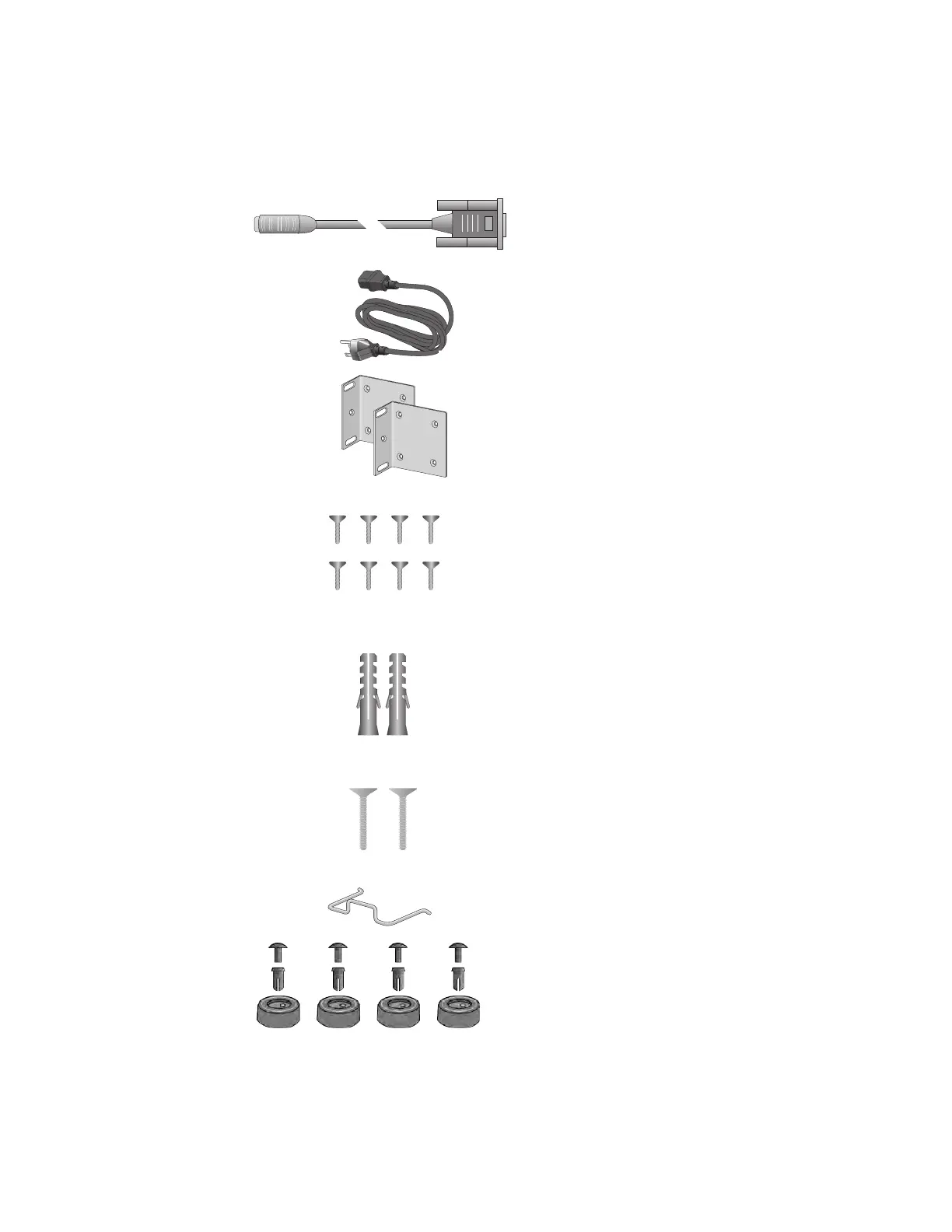
Figure 41 lists the items that are included in the accessory kit. Contact
your Allied Telesis sales representative for assistance if any item is
missing or damaged.
Figure 41. Accessory Kit Items
Two or four wall/equipment rack
brackets depending on model
1417
One 2m (6.6 ft) local management
cable with RJ-45 (8P8C) and DB-9
(D-sub 9-pin) connectors
Eight or sixteen screws for
attaching the wall/equipment rack
brackets depending on model:
Length: 6.0mm (0.2 in.)
Diameter: 4.0mm (0.2 in.)
One regional AC power cord
Two or four anchors for concrete
walls depending on model:
Length: 29.6mm (1.2 in.)
Diameter: 6.0mm (0.2 in.)
Two or four screws for wood or concrete
walls depending on model:
Length: 32mm (1.3 in.)
Diameter: 4mm (0.2 in.)
3375
1570
One power cord retaining clip
Four rubber bumper feet

 Loading...


