GS980MX Series Installation Guide for Virtual Chassis Stacking
95
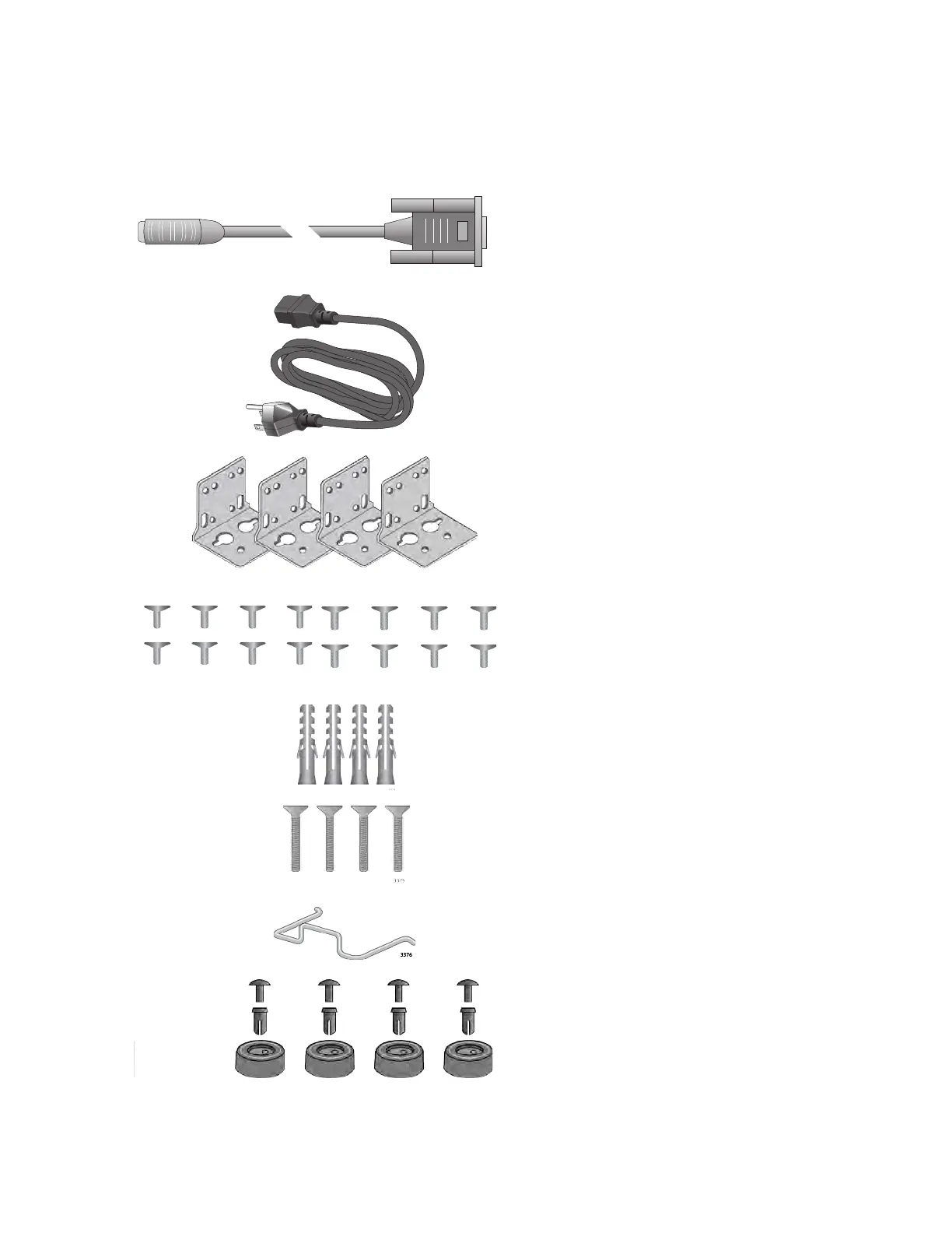
Figure 36 here and Figure 37 on page 96 list the items in the accessory kit.
Contact your Allied Telesis sales representative for assistance if any item
is missing or damaged.
Figure 36. GS980MX/10HSm Accessory Kit
One 2m (6.6 ft) local management
cable with RJ-45 (8P8C) and DB-9 (D-
sub 9-pin) connectors.
Sixteen screws for attaching the
BRKT-J24 wall brackets to the
switch.
Length: 6.0mm (0.2 in.)
Diameter: 4.0mm (0.2 in.)
One regional AC power cord
Four anchors for concrete walls:
Length: 29.6mm (1.2 in.)
Diameter: 6.0mm (0.2 in.)
Four screws for wood or concrete
walls:
Length: 32mm (1.3 in.)
Diameter: 4mm (0.2 in.)
Power cord retaining clip
Four BRKT-J24 wall mounting
brackets
Four rubber bumper feet

 Loading...


