Chapter 7: Building the Trunk with the Default 10Gbps Stacking Ports
146
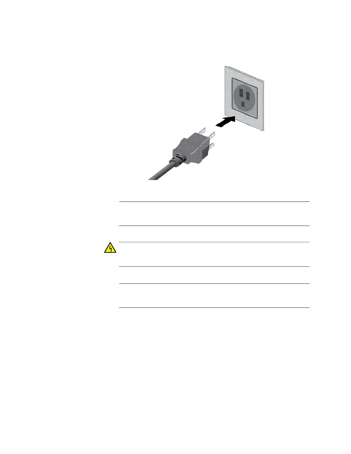
4. Connect the power cord to an appropriate power source. Refer to
“Power Specifications” on page 249 for the power specifications of the
switches.
Figure 81. Plugging in the AC Power Cord to an AC Source
Note
The illustration shows a North American power cord. Your power
cord may be different.
Warning
Power cord is used as a disconnection device. To de-energize
equipment, disconnect the power cord. E3
Note
Pluggable Equipment. The socket outlet shall be installed near the
equipment and shall be easily accessible. E5
5. Wait one minute for the switch to initialize its management software.
The switch should be displaying the number 1 on its ID LED.
6. Repeat step 1 through 4 to power on the switch to be assigned ID
number 2.
7. Wait two minutes for the new switch to join the stack as a member.
As the new switch boots up, the first switch, which has the ID number 1
and at this point is the master switch of the stack, notifies the new
switch that its current ID number is already being used and that it

 Loading...


