GS980MX Series Installation Guide for Virtual Chassis Stacking
137
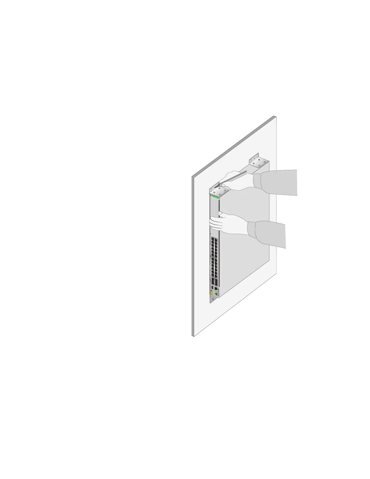
4. Follow these guidelines as you position the switch on the wall:
Position it so that the front panel is facing left or right. Refer to
Figure 68 on page 124. Do not install the switch with the front panel
facing up or down.
Provide sufficient space from other devices or walls so that you can
access the front and back panels, and for adequate air flow and
ventilation.
Figure 76. Marking the Locations of the Bracket Holes on a Concrete Wall
5. Place the switch on a table.
6. Use a drill and a 1/4-inch carbide drill bit to pre-drill the holes you
marked in step 3. Please review the following guidelines:
Prior to drilling, set the drill to hammer and rotation mode. The
modes break up the concrete and clean out the hole.
Clean out the holes with a brush or compressed air.
35179111315171921 23 27/S1
28/S2
25 SFP+
26
AT-GS980MX/28
16 18 2014
10G/1G
46810122 22 24
FDX HDX COL
1G LINK ACT 100 LINK ACT 5G/2.5G/1G LINK ACT 100 LINK ACT
PORTS 21-24
PORTS 1-20
5G/2.5G/1G/100
CLASS1
LASER PRODUCT
CONSOLE
4596

 Loading...


